background image

16-Channel Digital Video Recorder 


57 


If the DVR’s time and date have been reset to a time that is earlier than some recorded video, it is possible for the DVR 
to have more than one video stream in the same time range.  Move to 

Select a Segment

, and select the video stream you 

want to search.  Refer to the 

Appendix – Time Overlap

 for further information on searching time-overlapped video streams.


NOTE:  The lower number of the Segment indicates the latest recorded video.


Once you have set the date and time you want to search, highlight 

Go

 and press the   button.  The selected date and 

time will display. 


NOTE:  It is possible that no recorded image displays on the current screen.  Press the 

DISPLAY

 button and change 

the screen mode to 4x4.  You will be able to easily see the camera have recorded video during target time.
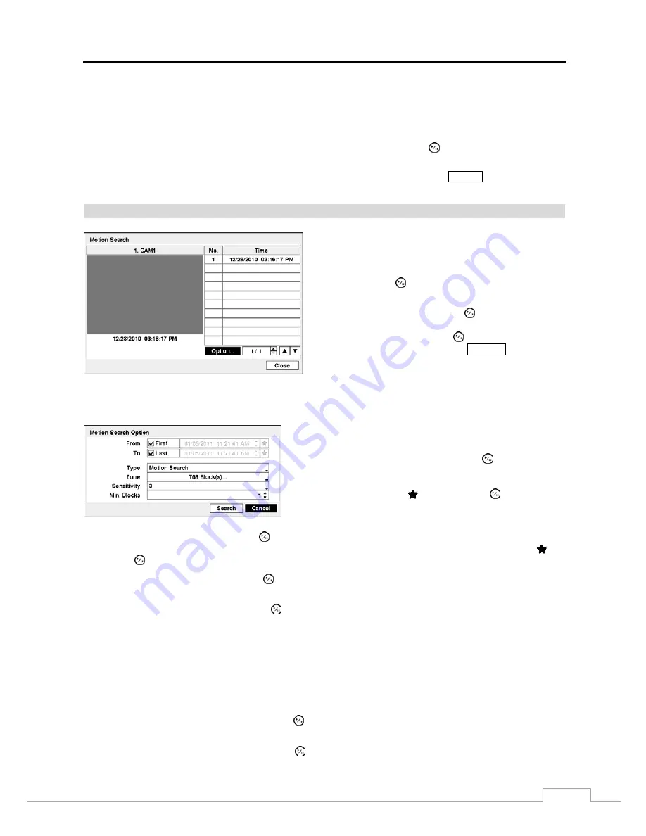


Motion Search 


Figure 69 — Motion Search screen. 

The 

Motion Search…

 can be selected from the Search menu 

while the DVR displays the camera full screen.  The 

Motion 

Search

 screen displays a list of motion events.  Use the arrow 

buttons to highlight the event for which you would like to see 
video and press the   (Play/Pause) button to display the video 
associated with the selected event on the small search screen. 


Highlighting 

Close

 and pressing the   button will extract the 

video associated with the Motion event and display the first 
image of the event.  Pressing the   button will start playing 
the “event” video segment.  Pressing 

SEARCH

 returns to live 

monitoring. 


You can also narrow your event search by selecting the 

Option…

 button and setting up the new search condition. 


You can search video from the first to last recorded images, or 
you can set the start and stop times and dates. 


Highlight the box beside 

From 

and press the   button to toggle 

between On and Off.  When set to Off, you can enter a specific Date 
and Time.  When set to On, the search will be from the first recorded 
image.  When highlighting   and pressing the 


button the 

bookmark list displays and the bookmark point you selected will 
be the starting date and time. 


Highlight the box beside 

To 

and press the   button to toggle between On and Off.  When set to Off, you can enter a 

specific Date and Time.  When set to On, the search will be from the last recorded image.  When highlighting   and 
pressing the 


button the bookmark list displays and the bookmark point you selected will be the ending date and time.


Highlight the box beside 

Type

 and press the   button.  You can select between 

Motion Search 

and 

Museum Search

.  

Motion Search


detects motion in the defined area.  

Museum Search 

detects if a defined object has moved. 


Highlight the box beside 

Zone 

and press the   button.  An image from the video appears with a grid overlaid.  You 

can turn sensor blocks On and Off to define the area of the picture in which you want to search for motion. 


NOTE:  Defining the area of the image in which you want to search for motion is nearly identical to setting up 

the DVR for Motion Detection.  Please refer to Motion Detection Screen in Chapter 3 — Configuration for 
more detailed instructions on setting up the detection blocks.


When setting the Museum Search Zone, the zone should be placed inside of the border line of the target 
object.  If the selected block is placed on the border line, the sensitivity of the Museum Search may decrease. 


The zone should be placed or focused on the centre or, at least, within the outline of targeted object. 


Highlight the box beside 

Sensitivity 

and press the   button.  You will be able to select from 

1

 (low sensitivity) to 

5


(high sensitivity). 


Highlight the box beside 

Min. Blocks 

and press the   button.  You will be able to set the number of sensor blocks that 

must be activated.  Setting the Min Blocks will only be available if Motion Search is selected. 

Содержание VLDVR Series

Страница 1: ......

Страница 2: ...NT GENERATES USES AND CAN RADIATE RADIO FREQUENCY ENERGY AND IF NOT INSTALLED AND USED IN ACCORDANCE WITH THE INSTRUCTION MANUAL MAY CAUSE HARMFUL INTERFERENCE TO RADIO COMMUNICATIONS OPERATION OF THI...

Страница 3: ...fied service personnel under the following conditions A When the power supply cord or the plug has been damaged B If liquid is spilled or objects have fallen into the equipment C If the equipment has...

Страница 4: ...er 3 Configuration 7 Front Panel Controls 7 Camera Buttons 1 to 16 7 HDD LED 7 Alarm LED 8 Arrow Buttons 8 Play Pause Button 8 MENU Button 8 PTZ Zoom Button 8 Group Sequence Button 8 Search Button 9 D...

Страница 5: ...Schedule 33 Pre Event 35 Event Setup 35 Alarm In 36 Motion Detection 37 Video Loss 39 Video Blind 39 Text In 41 System Event 42 Event Status 44 Chapter 4 Operation 45 Turning on the Power 45 Live Mon...

Страница 6: ...DVR front panel 7 Figure 4 Infrared remote control 10 Figure 5 Login screen 12 Figure 6 Logout screen 12 Figure 7 Setup screen 13 Figure 8 System menu 13 Figure 9 Information setup screen 14 Figure 10...

Страница 7: ...e 47 Motion Detection Settings screen 37 Figure 48 Motion Detection Actions screen 38 Figure 49 Video Loss Settings screen 39 Figure 50 Video Loss Actions screen 39 Figure 51 Video Blind Settings scre...

Страница 8: ...iew In addition to replacing both a time lapse VCR and a multiplexer in a security installation your DVR has many features that make it much more powerful and easier to use than even the most advanced...

Страница 9: ...User s Manual 2 Figure 1 Typical DVR installation...

Страница 10: ...ired to install the DVR Refer to the installation manuals for the other items that make up part of your system Figure 2 DVR rear panel Video Input Video Out Audio In Out Power Cord Connector RS232 Por...

Страница 11: ...S232 Port Connector Pin Outs Master Unit Slave Unit RX To TXD TX To RXD GND To GND NOTE Refer to the following for pin out details for the 9 pin connector of the slave unit Male Female Pin 2 RXD eceiv...

Страница 12: ...eset Switch The DVR has a Factory Reset switch to the right of the VGA connector on the rear panel This switch will only be used on the rare occasions that you want to return all the settings to the o...

Страница 13: ...the VGA connector 4 Hold the switch until all the LEDs on the front panel are lit NOTE When the DVR successfully resets to factory defaults all the LEDs on the front panel flash five times 5 Release...

Страница 14: ...alarm output including the internal buzzer when the alarm is activated However when you are in the menu or PTZ mode you have to exit the menu or PTZ mode first to reset alarm output The infrared sens...

Страница 15: ...on In the Live Monitoring mode and Search mode pressing the MENU button displays the menu icons at the top of the screen Pressing the button again hides the menu icons During menu setup pressing the b...

Страница 16: ...ressing the DISPLAY button toggles between different display formats The available formats are PIP 2x2 1 5 1 7 3x3 and 4x4 Panic Button Pressing the PANIC button starts panic recoding of all camera ch...

Страница 17: ...ons Refer to the System Information setup screen in this chapter for further information on setting the System ID If the system ID is 1 to 16 you must to press the ID button and then press the number...

Страница 18: ...en displays when the DVR is playing back video Fast Forward Pressing the button plays video forward at high speed Pressing the button again toggles the playback speed from and Stop Pressing the button...

Страница 19: ...its default settings After you are finished with any setup screen you can highlight Save and press the button to save the changes and exit the screen If you do not wish to save the changes highlight...

Страница 20: ...e name or title and press the button That character appears in the title bar and the cursor moves to the next position Pressing toggles between the upper and lower case keyboards backspaces and delete...

Страница 21: ...pears The screen displays the upgrade package file names that are available The rui indicates that the file is for software upgrades and ofi indicates that the file is for optical drive firmware upgra...

Страница 22: ...me Highlight Date Time in the System menu and press the button The Date Time setup screen appears Figure 10 Date Time setup screen Highlight the first box beside Date and press the button The individu...

Страница 23: ...the IP address or domain name of the time server Highlighting allows you to select your time server from a list of registered time servers NOTE You can use the domain name instead of IP address if yo...

Страница 24: ...ice The Disk Bad column displays the percentage of bad sectors Not Formatted The device is not formatted Good Less than user defined percentage of bad disk sections is damaged Bad More than user defin...

Страница 25: ...f Highlighting the individual authority level boxes and pressing the button will toggle between that authority level being turned On and Off The authority levels that can be turned On and Off are Shut...

Страница 26: ...can also be set to never automatically login a user Highlighting the box beside Auto Logout allows you to select from a list of times that the user will be automatically logged out The options are Ne...

Страница 27: ...d Recording Profile Longer Recording Time Priority Profile NOTE The higher quality setting requires more storage space NOTE The recording resolution will be set to Very High when selecting High Video...

Страница 28: ...al Configuration for network configuration and then select the Test button to test the network configuration you selected NOTE Selecting Auto Configuration allows the DVR to automatically obtain LAN p...

Страница 29: ...Check otherwise the DVRNS changes will not be saved NOTE When entering no name or a name already registered on the DVRNS server an error message displays Select the Finish button to finish the Setup W...

Страница 30: ...the box beside Remote Audio Channel and pressing the button allows you to select the audio channel that sends audio to the remote site Selecting Select From ATVision will send audio of the channel sel...

Страница 31: ...rease the number The factory default Port settings are Remote Admin 8200 Remote Callback 8201 Remote Watch 8016 Remote Search 10019 Remote Audio 8116 NOTE Do NOT use the same port number for two diffe...

Страница 32: ...nd press the button A virtual keyboard appears allowing you to enter the DVR name to be registered on the DVRNS server Highlight the Check box and press the button to check whether or not the name you...

Страница 33: ...o send an email or to contact a computer running ATVision Remote Management Software when an event occurs Highlight Notification in the Network menu and press the button The Notification screen displa...

Страница 34: ...l address Highlight the Test box and press the button to test emailing with the current settings you made Highlight the Callback tab and the Callback screen displays Highlight Enable and press the but...

Страница 35: ...TZ setup screen displays NOTE You will only be able to set up PTZ devices if the PTZ port is set to RS232 or RS485 Figure 30 Camera PTZ setup screen Highlight the box in the Product column for the PTZ...

Страница 36: ...ox under the Title heading and pressing the button A virtual keyboard appears allowing you to enter the title Highlighting the box beside Dwell Time and pressing the button allows you to set the dwell...

Страница 37: ...ision via Ethernet Freeze Sequence The icon displays while in the Freeze mode and the displays while in the Sequence mode Screen Group The number of screen group displays when the DVR is not in the 4x...

Страница 38: ...s can be done with one camera displayed full screen while displaying the cameo window as a PIP picture in picture or displaying the cameras in a grid pattern with the bottom right window as the cameo...

Страница 39: ...garding event recording Highlighting De Interlace and pressing the button toggles between On and Off When set to On the DVR will turn the de interlace filter on while recording video with Very High D1...

Страница 40: ...Figure 40 Panic Record screen Highlighting Use Panic Recording and pressing the button toggles between On and Off Highlight the Panic Recording Duration box and set the duration of panic recording Pan...

Страница 41: ...Event mode the red icon displays at the top left corner of the screen The DVR will record and displays the icon at the top left corner of the screen when any event occurs When the DVR is in the Pre Ev...

Страница 42: ...ld like to record for the associated event Advanced Mode Only Pre Event Highlight Pre Event in the Record menu and press the button and the Pre Event setup screen appears If you do not have Event set...

Страница 43: ...its alarm input connectors Highlight the desired box under the Record heading and press the button A list of cameras appears Select the cameras that you want the DVR to record whenever it detects an...

Страница 44: ...t up motion detection zones by selecting or clearing blocks NOTE You can set up motion zones one block at a time in groups of 16 individual block groups A block group is positioned within the image ar...

Страница 45: ...the button A list of cameras appears You can associate as many cameras with that camera as you wish If the DVR detects motion on the selected camera it starts recording video from all the associated c...

Страница 46: ...all the associated cameras NOTE For the Record action the camera you select should be set to the Event or Time Event recording mode in the Record Schedule setup screen Highlight the box under the Ala...

Страница 47: ...evices and or move PTZ cameras to preset positions Highlight the box under the Record heading and press the button A list of cameras appears You can associate as many cameras with that camera as you w...

Страница 48: ...data might be lost when the text in buffer is filled by simultaneous text in transactions from all 16 LAN channels Highlight Setup and press the button Use the ATM or POS manufacturer s recommended s...

Страница 49: ...number of different devices and or move PTZ cameras to preset positions Highlight the box beside Record and press the button A list of cameras appears You can associate as many cameras with the Text...

Страница 50: ...ant the DVR to run self diagnostics on Alarm Inputs You can select from 1 hr to 30 days or Never Highlight the Storage tab and the Storage screen displays Figure 57 Storage screen Highlight the box be...

Страница 51: ...fy action to work the DVR should be registered in the ATVision Remote Management Software Event Status Highlight Event Status in the Event menu and press the button The Event Status screen appears Fig...

Страница 52: ...3 Configuration Turning on the Power Once you have installed the DVR following the instructions in Chapter 2 Installation it is ready to record Live Monitoring As soon as the DVR completes its initial...

Страница 53: ...equence monitoring should be selected in the Display setup screen Main Monitor tab Camera Menu Selecting Camera Menu in the Live Monitoring menu displays the following Camera Menu Audio Selecting Audi...

Страница 54: ...cting Exit Group Edit in the cameo menu displayed when pressing the MENU button also exits the Active Cameo mode The active cameo mode will remains in effect for 15 seconds if there is no further oper...

Страница 55: ...dvanced PTZ in the menu displaying at the top of the screen displays the Advanced PTZ menu Set the feature you wish to control by selecting it from the menu Refer to the camera manufacturer s instruct...

Страница 56: ...tatus icons will be displayed on the monitor If a camera is set up as Covert 2 in the Camera setup screen Settings tab that camera appears to be Off unless a user with Covert Camera View authority log...

Страница 57: ...size by using the mouse select the PIP and then click the right mouse button to display the following menu Select the options you want You can also change the location of the PIP by clicking the left...

Страница 58: ...o of the selected camera When in the single screen display format the camera currently displayed on the screen will be selected and when in the PIP display format the camera displayed on the PIP scree...

Страница 59: ...hen the DVR is playing back video Zoom Button Pressing the ZOOM button zooms in the current image on the screen DISPLAY Button Pressing the DISPLAY button toggles different display formats The availab...

Страница 60: ...and press the button The selected date and time will display If no video was recorded during the selected time a message appears alerting you that no image was recorded at that time The button and ar...

Страница 61: ...h Search authority logs into the system Pressing the Play Pause button will extract the event video and display the first image of the event Pressing the button will start playing the event video segm...

Страница 62: ...elect the text in devices which you want any reports of text input Highlight the box beside Record Channels and press the button You can select the cameras that you want to search for any reports of e...

Страница 63: ...dicates different recording modes Red for Panic Yellow for Pre Event Purple for Event and Blue for Time Selecting located at the bottom displays the Calendar Search screen See the following Calendar S...

Страница 64: ...n and Off When set to Off you can enter a specific Date and Time When set to On the search will be from the first recorded image When highlighting and pressing the button the bookmark list displays an...

Страница 65: ...et to On the search will be from the first recorded image When highlighting and pressing the button the bookmark list displays and the bookmark point you selected will be the starting date and time Hi...

Страница 66: ...more than three seconds while in the Search mode or Live Monitoring mode initiates the One Touch Clip Copy function The last recorded image will be the ending point of video to be clip copied and the...

Страница 67: ...cting Close When selecting Close Clip Copy continues and a confirmation screen will display when complete NOTE The file size for clip copy is limited to 30GB When copying video clips larger than 2GB t...

Страница 68: ...SB hard disk drive in Windows 98 NOTE Preparing a USB hard disk drive under Windows ME is almost identical to Windows 98 1 Connect the USB hard disk drive to your computer using the USB Cable 2 Turn o...

Страница 69: ...nt to search for Coke with a Qty Quantity of more than 1 and Hotdog with an amount totaling over 8 the following search condition can be set Search Example II 1 2 3 4 5 6 12345678901234567890123456789...

Страница 70: ...R IP address and the ATVision port number default 12088 set in the Network setup screen ATVision tab Or http DVRNS server address DVR name The DVRNS server address and the DVR name registered on the D...

Страница 71: ...ght mouse button on the Internet Explorer icon and select the Run as administrator option from the context menu Otherwise some functions of the ATVision might be limited to use There might be a proble...

Страница 72: ...ion with the remote site When the audio control panel displays click the to send audio to the connected remote site and click the button again to stop sending audio Click the to monitor live audio fro...

Страница 73: ...nd within the time parameters The Timetable window located at the bottom displays the time information for the image of the date selected on the calendar If more than one video stream in the same time...

Страница 74: ...e range In this case you can search overlapping video streams individually by selecting a specific segment For example when the DVR has recorded video from one to five o clock and the user changes the...

Страница 75: ...User s Manual 68 Map of Screens...

Страница 76: ...tem the DVR keeps rebooting and the upgrade fails If the current system version is higher than the upgrade package file version you should reset the DVR first using the Factory Reset When using the Fa...

Страница 77: ...3 No executable file 303 Saving remote package failed 14 Opening executable file failed 304 Remote upgrade is cancelled by the user 15 Writing executable file failed 400 USB device mounting failed 16...

Страница 78: ...larm Input Output Terminal Blocks Ethernet Port RJ 45 RS232 Serial Port Two connector terminal block RS485 Serial Port Two connector terminal block IR Port 1 Remote Control USB Port 2 USB 2 0 STORAGE...

Отзывы: