AT-UHD-PRO3-1616M
54
IR Control
Advanced Operation
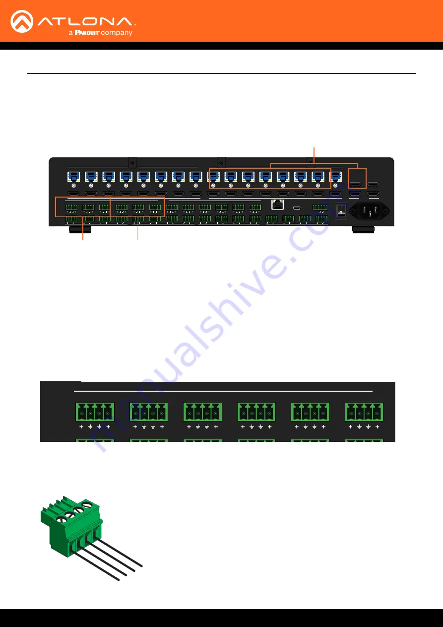
The AT-UHD-PRO3-1616M feature eight
IR IN
ports and eight
IR OUT
ports. Devices at either the headend or
connected to the receiver unit can be controlled using IR.
The following shows how to control displays (or other sink devices) which are connected to an HDBaseT receiver.
Each IR IN port provides IR control for two individual HDBaseT receivers (outputs).
AT-UHD-PRO3-1616M
FCN
CANCEL
EDID
INFO
POWER
ENTER
5
6
7
8
1
2
3
4
HDBaseT OUT
1ED
2ED
3ED
4ED
5ED
6ED
7ED
8ED
9
10
11
12
13
14
15
16
1
2
3
4
5
6
7
8
9
10
11
12
13
14
15
16
17
18
19
20
HDMI OUT
AUDIO OUT
1
L
R
2
L
R
3
L
R
4
L
R
5
L
R
6
L
R
7
L
R
8
L
R
9
L
R
10
L
R
11
L
R
12
L
R
1
2
3
4
5
6
7
8
9
10
11
12
13
14
15
16
1
2
3
4
5
6
7
8
IR OUT
IR IN
S
S
S
S
S
S
S
S
S
S
S
S
S
S
S
S
S
S
S
S
S
S
S
S
S
S
S
S
S
S
S
S
IR IN
RS-232
MAIN
RX TX
S
LAN
FW
OFF
ON
PWR: 100-240VAC 50/60Hz
HDMI IN
9
10
11
12
13
14
15
16
IR IN
IR OUT
ZONE OUT
Cable Assembly
1.
Remove at least 3/16” (5 mm) of insulation from both the GND and Signal leads.
2.
Locate the included 4-pin captive screw block and open each of the terminals by turning the screws counter-
clockwise, using a small regular screwdriver.
AT-UHD-PRO3-1616M
FCN
CANCEL
EDID
INFO
POWER
ENTER
5
6
7
8
1
2
3
4
HDBaseT OUT
1ED
2ED
3ED
4ED
5ED
6ED
7ED
8ED
9
10
11
12
13
14
15
16
1
2
3
4
5
6
7
8
9
10
11
12
13
14
15
16
17
18
19
20
HDMI OUT
AUDIO OUT
1
L
R
2
L
R
3
L
R
4
L
R
5
L
R
6
L
R
7
L
R
8
L
R
9
L
R
10
L
R
11
L
R
12
L
R
1
2
3
4
5
6
7
8
9
10
11
12
13
14
15
16
1
2
3
4
5
6
7
8
IR OUT
IR IN
S
S
S
S
S
S
S
S
S
S
S
S
S
S
S
S
S
S
S
S
S
S
S
S
S
S
S
S
S
S
S
S
IR IN
RS-232
MAIN
RX TX
S
LAN
FW
OFF
ON
PWR: 100-240VAC 50/60Hz
HDMI IN
9
10
11
12
13
14
15
16
Signal
Signal
GND
GND
3. Insert the GND and Signal leads into correct terminal, as shown, and tighten the screws to secure each wire.
Do no overtighten.
4. Connect the captive screw connector to the
IR IN
ports on the AT-UHD-PRO3-1616M.


