D 3.1 13
D_3
.1_0
1_G
B.
fm
1
3
-1
6
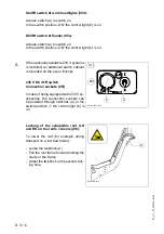
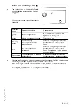
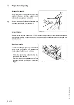
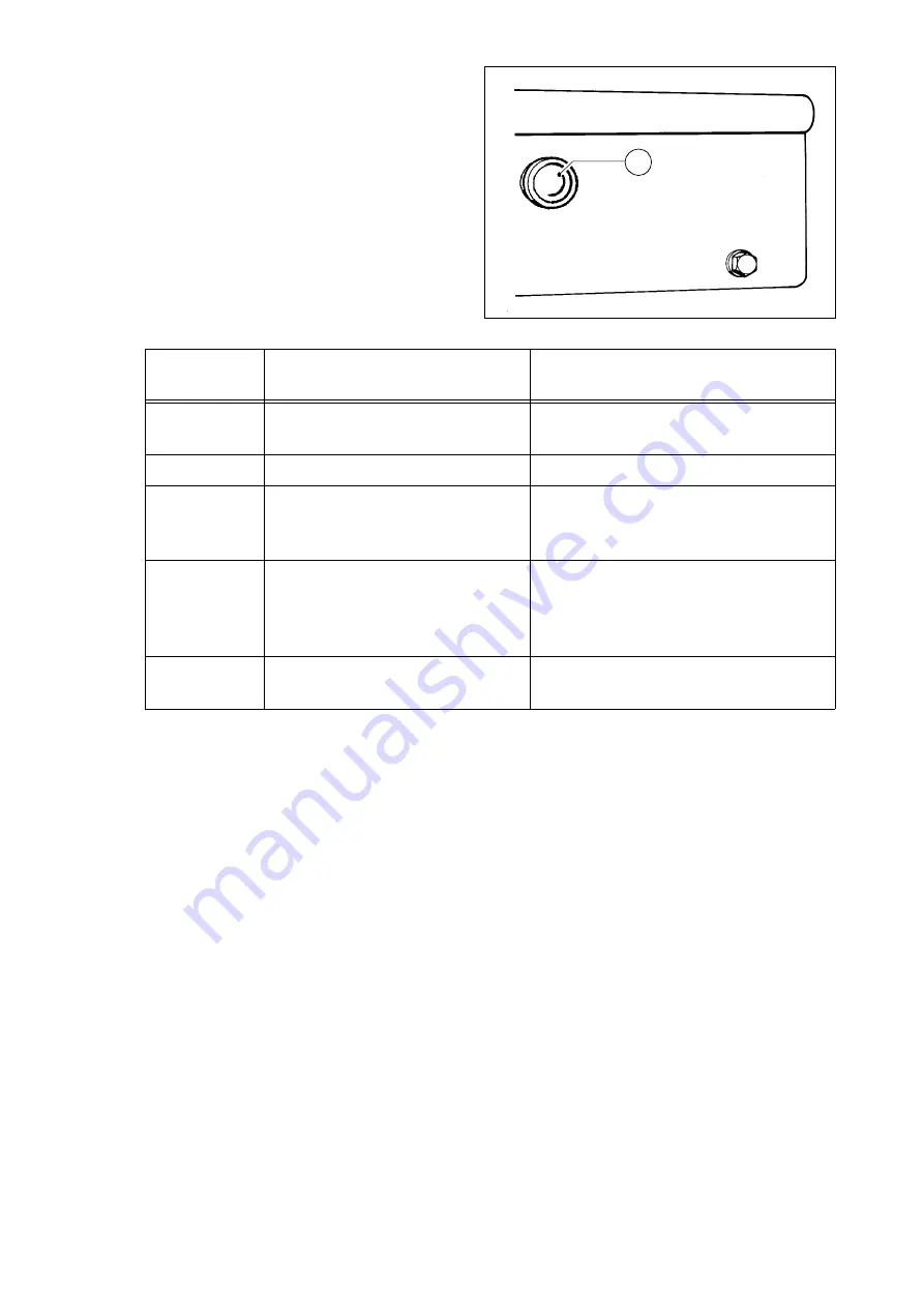
Particle filter - control light (102) (
o
)
A
The control light of the particle filter is
found under the control track of the oper-
ating panel.
When observing the control light (a) it is
essential:
A
With the brief increase of the engine speed to the max. range, the filter is cleaned au-
tomatically due to the higher temperature of the exhaust fume.
If the control light still fails to turn on for this action, the filter needs to be cleaned.
See chapter „Maintenance“ for cleaning the particle filter.
Indicator
colour
Operating condition
Cause / action
yellow
No counterpressure
No counterpressure Check the
tightness of the system.
green
Within the measuring range
There is no fault
flashing
green
Treshold range -
Counterpressure in the
warning range
Increase of engine speed to raise
the temperature of the exhaust
fume.
red
Set value achieved /
exceeded
Increase of engine speed to raise
the temperature of the exhaust
fume. If necessary, clean / replace
the particle filter.
flashing red
The temperature or pressure
sensor failed
Check and replace, as required,
the temperature / pressure sensor
Partikellight.tif
a
Содержание DYNAPAC Svedala Demag DF 115 C
Страница 2: ...VALUE QUALITY THE ORIGINAL Your Authorized Dynapac Dealer...
Страница 10: ......
Страница 18: ......
Страница 20: ......
Страница 44: ......
Страница 58: ......
Страница 62: ...D 1 4 4 D_1 4_01_GB fm 4 22 Element2_konv_Kette_635 bmp 9 12 9a 5 8 14 A 6 7 13...
Страница 64: ...D 1 4 6 D_1 4_01_GB fm 6 22 Element2_konv_Kette_635 bmp 9 12 9a 5 8 14 A 6 7 13...
Страница 66: ...D 1 4 8 D_1 4_01_GB fm 8 22 Element2_konv_Kette_635 bmp 27 19 18 17 28 29 B 16 25 26 22 21 20 23 24...
Страница 68: ...D 1 4 10 D_1 4_01_GB fm 10 22 Element2_konv_Kette_635 bmp 27 19 18 17 28 29 B 16 25 26 22 21 20 23 24...
Страница 70: ...D 1 4 12 D_1 4_01_GB fm 12 22 Element2_konv_Kette_635 bmp 27 19 18 17 28 29 B 16 25 26 22 21 20 23 24...
Страница 96: ......
Страница 120: ...D 4 6 24 D_4 6_01_GB fm 24 38 2 2 Error messages...
Страница 121: ...D 4 6 25 D_4 6_01_GB fm 25 38...
Страница 122: ...D 4 6 26 D_4 6_01_GB fm 26 38...
Страница 123: ...D 4 6 27 D_4 6_01_GB fm 27 38...
Страница 124: ...D 4 6 28 D_4 6_01_GB fm 28 38...
Страница 125: ...D 4 6 29 D_4 6_01_GB fm 29 38 2 3 FMI codes...
Страница 134: ......
Страница 146: ...E 01 12 E_01_GB fm 12 18 3 Auger extension auger type II Auger_DEM bmp...
Страница 147: ...E 01 13 E_01_GB fm 13 18 3 1 Mounting extension parts Sch_ver1 tif Sch_ver2 tif 16 5 9 10 8 7 6 14 15 12 11 12 5...
Страница 152: ......
Страница 154: ......
Страница 155: ...F_2 3_01_GB fm 1 2 F 2 3 1 F 2 3 Maintenance overview 1 Maintenance review 7 2 4 1 3 5 1 6 8 9 10...
Страница 157: ...F 3 0 1 F_3 0_01_GB fm 1 4 F 3 0 Maintenance Conveyor 1 Maintenance Conveyor...
Страница 161: ...F 4 1 1 F_4 1_01_GB fm 1 8 F 4 1 Maintenance Auger 1 Maintenance auger sub unit...
Страница 168: ......
Страница 180: ......
Страница 181: ...F 6 0 1 F_6 0_01_GB fm 1 8 F 6 0 Maintenance Hydraulic system 1 Maintenance hydraulic system...
Страница 189: ...F 7 2 1 F_7 2_01_GB fm 1 4 F 7 2 Maintenance Running gear 1 Maintenance running gear 635_ISO_Dyn bmp LW_DEM_inter bmp 43...
Страница 193: ...F 8 1 1 F_8 1_01_GB fm 1 20 F 8 1 Maintenance Electronic System 1 Maintenance Electronic System...
Страница 220: ......
Страница 221: ...F 10 0 1 F_10 0_01_GB fm 1 6 F 10 0 Checks decommissioning 1 Tests check up cleaning stopping...
Страница 226: ......

