background image

Manual, Control Module, PROFINET, DL10
Document #9620-20-C-DL10-04

Pinnacle Park • 1031 Goodworth Drive • Apex, NC 27539 • Tel: 919.772.0115 • Fax: 919.772.8259 • 

www.ati-ia.com

C-41

6.  Troubleshooting and Service Procedures

The following section provides troubleshooting information to help diagnose conditions with the Tool Changer or 
Utility Coupler and service procedures to help resolve these conditions.

WARNING: 

Do not perform maintenance or repair(s) on the Tool Changer or modules unless 

the Tool is safely supported or placed in the tool stand, all energized circuits (e.g. electrical, 
air, water, etc.) are turned off, pressurized connections are purged and power is discharged 
from circuits in accordance with the customer’s safety practices and policies. Injury or 
equipment damage can occur with the Tool not placed and energized circuits on. Place the 
Tool in the tool stand, turn off and discharge all energized circuits, purge all pressurized 
connections, and verify all circuits are de-energized before performing maintenance or 
repair(s) on the Tool Changer or modules. 

6.1  Troubleshooting

Refer to the following table for troubleshooting information.

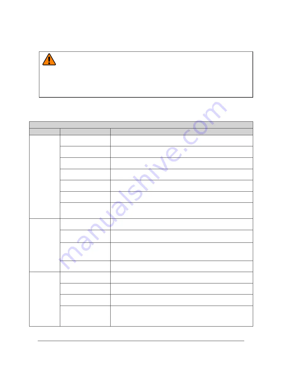
Table 6.1—Troubleshooting

Symptom

Possible Cause 

Correction

Unit will not 
lock or unlock

Debris caught between the 
Master and Tool plates. 

Clean debris from between Master and Tool plates. Verify mounting fasteners is 
secure and does not protrude above the mating surfaces. 

Ball bearings are not 
moving freely.

Verify that ball bearings are moving freely. Clean and lubricate as needed. 

Refer 

to the Maintenance section of the Tool Changer manual for instructions.

Air supply not to 

specifications.

Check air supply. 

Refer to Pneumatic Connection section of the Tool Changer 

Manual


for specifications.

Exhaust port is not 
properly vented.

Check that exhaust port is properly vented. 

Refer to Pneumatic Connection 

section of the Tool Changer Manual for valve requirements.

Incorrect valve operation.

Check valve for proper operation. 

Refer to Pneumatic Connection section of the 

Base Tool Changer Manual for valve requirements.

Signals are mapped 
incorrectly.

Verify that signals are mapped and are communicating properly. Refer to 

Section 9—Drawings 

for electrical schematic.

Master and Tool are within 

the specified No‑Touch 

zone.

Verify that the Master and Tool are within the specified No‑Touch zone when 

attempting to lock. 

Refer to the Operation Section of the Tool Changer manual 

for specifications.

Sensors not 
operating 
properly (but 
PROFINET 
is operating 
correctly).

Sensor cables damage or 
incorrectly connected.

Verify that cables are connected correctly and not damaged, replace if 
damaged. 

Refer to the Troubleshooting Section of the Tool Changer manual.

Sensors are not set 
correctly.

Verify that the sensors are set correctly. 

Refer to the Troubleshooting Section of 

the Tool Changer manual.

Tool plate is not secured 
properly or debris is 
trapped between surfaces.

Ensure that the Tool plate is securely held to the Master plate, that nothing is 
trapped between their surfaces.

Air trapped in the unlock 
(U) air port.

Ensure that there is no air trapped in the Unlock (U) air port. 

Refer to Pneumatic 

Connection section of the Tool Changer Manual for valve requirements.

Loss of 
communication

Contaminated or loose 
cable connections.

Ensure all cable connections are clean and tight.

Damaged signal cabling

Check/replace signal cabling upstream and downstream of Tool Changer 
modules.

Worn or damaged contact 
pins

Inspect module contact pins for debris/wear/damage. Contact ATI for contact 
pin replacement.

Product upstream 
and downstream of 
Tool Changer failed or 
damaged

Check product upstream and downstream of Tool Changer for failure. This 
failure can “appear” to be caused by the Tool Changer or affect Tool Changer 
performance.

Содержание PROFINET DL10

Страница 1: ...3 Ethernet 1 and Ethernet 2 LEDs C 12 2 1 4 Integrated Ethernet Switch C 12 2 1 5 Reset To Factory Push Button C 13 2 2 Arc Prevention Circuit C 13 2 2 1 Arc Prevention Circuit Behavior during Couplin...

Страница 2: ...6 4 Operation C 27 4 1 Lock Unlock and RTL Sensor Cable LED Behavior C 28 4 2 Inputs C 29 4 2 1 Locked C 29 4 2 2 Unlocked C 29 4 2 3 Input Logic Power Good C 29 4 2 4 Output Power Available C 29 4 2...

Страница 3: ...2 Service Procedures C 42 6 2 1 Seal Replacement C 42 6 2 2 DL10 Device Replacement Procedures C 43 6 2 2 1 Master Module Replacement Procedures C 43 6 2 2 2 Replace a Master Module with an Already C...

Страница 4: ...sor input is high UNLOCKED sensor input is low TOOL PRESENT input is high Output Power Available An input indicating the presence of US2 Power at the ATI Master PROFINET A communication system for Ind...

Страница 5: ...atch The output supplied to the ATI Master module to uncouple the Tool Changer Unlatch Enable Indicates it is safe to proceed with an unlatch request Unlocked A proximity sensor input indicating that...

Страница 6: ...and fixed contact pins on the Tool To avoid unintentional human contact the Master spring pins are recessed below an insulated surface on both the power and signal circuits When the modules are couple...

Страница 7: ...w The Tool module employs a series of 5 push button switches for setting of the Tool ID input that allows the customer to distinguish between the different tools that are used in a robotic cell or on...

Страница 8: ...r module Table 2 1 PROFINET Interface Parameters Parameter Description DCP supported Fast Startup supported Used Protocols subset UDP IP ARP ICMP Ping Topology recognition LLDP SNMP V1 MIB2 physical d...

Страница 9: ...l 1 0 Unlatch Enabled Unlatch Enabled Status Information 1 TSIV TSI Switch Verify 2 TSRV TSI Relay Verify 3 Reserved 4 RTLV1 Ready to Lock Relay 1 Verify 5 RTLV2 Ready to Lock Relay 2 Verify 6 to 7 Re...

Страница 10: ...Tool ID Switch3 Bit4 3 Tool ID Switch3 Bit8 4 Tool ID Switch4 Bit1 5 Tool ID Switch4 Bit2 6 Tool ID Switch4 Bit4 7 Tool ID Switch 4 Bit 8 6 0 Tool ID Switch5 Bit 1 N A 1 Tool ID Switch5 Bit2 2 Tool I...

Страница 11: ...ified on the module as BF It provides PROFINET status information Refer to Table 2 5 for an outline of this LED s operation Table 2 4 Master Module SF status LED Status LED Note No Power Off No power...

Страница 12: ...e is currently no data exchange activity Active RX TX Red flashing Green solid There is sporatic data exchange activity with the Ethernet PROFINET connection established Red solid Green solid There is...

Страница 13: ...ction 6 2 2 DL10 Device Replacement Procedures for a detailed device replacement procedure After the push button is pressed the SF LED will blink red indicating that with the next power cycle the Name...

Страница 14: ...n circuit is more fully described in the following sections 2 2 2 Arc Prevention Circuit Behavior during Coupling The behavior of the Arc Prevention circuit during coupling can be more clearly underst...

Страница 15: ...and the switching off of power designated T2 in the diagram is less than 50 ms Some time after power is turned off and the Master and Tool begin to separate electrical contact between Master and Tool...

Страница 16: ...on as the Tool Changer or Utility Coupler is coupled Typically the Tool ID information is available to the Master within 150 ms from the time the Tool Changer or Utility Coupler is coupled NOTICE When...

Страница 17: ...s both a firmware and a hardware interrupt for the Unlatch output bit Unlatch Enabled in the bitmap reports that the tool change will process an Unlatch command if issued Refer to Section 2 1 Master M...

Страница 18: ...tch Robot Arm Master Module Tool Module 4 Pin M12 Connector for TSI Limit Switch Tool Changer Tool Tool Stand Trip Dog Intregal to the Tool Stand Figure 2 7 DL15 Tool Stand Interlock TSI with a Contac...

Страница 19: ...2 5 1 1 RTL Bypass Relay Circuit The Master module has a normally closed RTL bypass circuit RTL relay If the Tool Changer is inadvertently locked without a Tool attached the Tool Changer can still be...

Страница 20: ...r is Coupled with the Tool and the Tool is in the Stand The Master and Tool are coupled in the tool stand and the Master has detected a Tool is present with the RTL1 and RTL2 sensors ON Thus opening t...

Страница 21: ...he TSI Switch Normally open is not made and thus breaking the TSI circuit and interrupting an UNLATCH command Figure 2 11 TSI Circuit with Master and Tool Locked and Free of Stand DL10 T Shown LATCH 2...

Страница 22: ...TL sensor signals with the TSIV input and enables the Unlatch output signal only if it meets the conditions in Table 2 8 Table 2 8 UNLATCH Enable Logic and Truth Table Inputs Output Status of Master B...

Страница 23: ...ners 3 1 Master Control Signal Module Installation Refer to Figure 3 1 Tools required 3 mm and 5 mm hex keys Supplies required Clean rag Loctite 242 M5 fastener for grounding terminal NOTICE If module...

Страница 24: ...r etc 4 Disconnect the L Lock U Unlock and R1 and R2 RTL sensor cable connectors from the Master module 5 Disconnect the power cable and PROFINET cable connectors from the Master module 6 Disconnect t...

Страница 25: ...er supplied fastener 12 After the procedure is complete resume normal operation Figure 3 2 Tool Module Installation DL10 T Shown Tool Changer Valve Adapter JR4 T Shown 2 M6 Socket Head Cap Screw Tool...

Страница 26: ...lastic stylus to press on the Tool ID push buttons to increase or decrease the digit value from 0 to 9 Set the Tool ID to the desired unique 5 digit number from 00000 to 99999 for each tool 3 Re insta...

Страница 27: ...processes CAUTION Improper cable routing can result in wires and cables being pinched in the joint between the Tool Changer plates and premature failure of the electrical connectors Properly route and...

Страница 28: ...plate attached RTL R1 Sensor ON OFF ON ON Unlock U Sensor RTL R2 Sensor ON OFF ON OFF Lock L Sensor Ready to Lock Tool Changer Master plate with Tool plate parallel and at a distance of 1 22 mm or le...

Страница 29: ...ay not properly latch 4 2 5 RTL1 and RTL2 Proximity sensor inputs indicate that the Tool Changer Master is close to the Tool and the Master and Tool are okay to couple These proximity sensors are inst...

Страница 30: ...e is monitored immediately after an UNLATCH command and will disable the Unlatch and turn off Unlatch immediately If UNLATCH is inadvertently held ON during a power cycle the UNSAFE_UNLATCH error will...

Страница 31: ...n UNLATCH output to Valve 1 Yes Clear Errors Bit SPARE Output Overload Reserved No Clear Errors Bit UNSAFE UNLATCH COMMAND Unlatch requested under unsafe conditions Yes Cycle the UNLATCH output bit or...

Страница 32: ...ilure BF LEDs or Section 2 1 3 Ethernet 1 and Ethernet 2 LEDs for possible issues 1 The robot and Tool Changer master are free of the stand or storage location the Tool Changer is uncoupled and the To...

Страница 33: ...hin 0 06 to 0 15 RTL R1 Unlock U RTL R2 Lock L Green LED Power Yellow LED Switch Made 0 06 to 0 15 Away SF LED is Green Could see Red Flashing But should turn Green E2 LED turns Green Then Red Flashin...

Страница 34: ...is Green Could see Red Flashing But should turn Green E2 LED turns Green Then Red Flashing Green Then Red Green BF LED is Off E1 LED is Red Green NOTICE If the LEDs don t match what is shown refer to...

Страница 35: ...turn the Unlatch output OFF and turn the Latch output ON Note Even for units with single solenoids the Latch output must be turned ON b With the Latch output ON power is available on the Tool and the...

Страница 36: ...tion 2 1 3 Ethernet 1 and Ethernet 2 LEDs for possible issues 6 The robot moves away from the tool stand with the Tool Changer coupled a The TSI Limit Switch is deactivated and the TSIV and TSRV input...

Страница 37: ...oves into the tool stand with the Tool Changer coupled a When the tool is returned to the stand the TSI Limit Switch is activated and the TSIV and TSRV inputs goes ON b The Unlatch Enabled is ON indic...

Страница 38: ...ble issues 10 The robot and Master move away from the tool are parallel and between 0 06 to 0 15 of the Tool a The Tool Present and TSIV and TSRV inputs turn OFF b The Tool ID is unavailable all 1 0xF...

Страница 39: ...d in dirty environments e g welding or deburring applications limit the exposure of the Tool Changer Idle Tool assemblies should be covered to prevent debris from settling on the mating surface Also t...

Страница 40: ...d Pins 5 If debris or darkened pins exist remove debris using a vacuum and clean using a nylon brush ATI Part Number 3690 0000064 60 NOTICE Do not use an abrasive media cleaners or solvents to clean t...

Страница 41: ...that exhaust port is properly vented Refer to Pneumatic Connection section of the Tool Changer Manual for valve requirements Incorrect valve operation Check valve for proper operation Refer to Pneuma...

Страница 42: ...ide instructions for inspection adjustment test or replacement of components 6 2 1 Seal Replacement Parts required Refer to Section 9 Drawings The seal protects the electrical connection between the M...

Страница 43: ...to Section 3 1 Master Control Signal Module Installation for installation procedure 6 2 2 2 Replace a Master Module with an Already Commissioned Master Module Tools required 5 mm Allen wrench Phillip...

Страница 44: ...M8 set screw 2 M6 Socket Head Cap Screw L Connector U Connector R2 Connector R1 Connector Valve Signal Pin Block LEDs and the Reset Switch Use the Ledge Mounting Feature to Properly Align the Module...

Страница 45: ...tion name and configured to the appropriate station name for your application or the network controller may be configured to automatically rename the module when it detects the default name 14 Disconn...

Страница 46: ...ND Microspheres 0 3 uncoated lead threads 5 7 coated threads IFI525 7 2 Tool Module Serviceable Parts Table 7 2 Tool Module Mounting Fasteners Part Number Qty Description 3500 1066016 21A 2 M6 x 16 So...

Страница 47: ...ch US2 20 4 V to 29 V limited by the valve for DL10 T and DL15 T Note The power source for input and output power must be capable of outputting an operating voltage that is overcurrent protected and r...

Страница 48: ...Pin Mini Connector for US1 and US2 power M12 5 Pin Female Connector provided to support RFID Based TSI on Tool Tool ID 0 99999 adjustable with thumbwheel switches Supports Arc Prevention on the Maste...

Страница 49: ...50 133 4 60 3 71 2 B Sht 2 Notes Pin block signal assignments shown on Sheet 2 1 Connector pin designations shown on Sheet 3 2 Serviceable parts for the DL10 are shown on Sheet 4 3 Electrical schemati...

Страница 50: ...Valve Signal Pin Block Rev Description Initiator Date See Sheet1 B 1 2 2 5 REVISION NOTES UNLESS OTHERWISE SPECIFIED DO NOT SCALE DRAWING ALL DIMENSIONS ARE IN MILLIMETERS DRAWN BY CHECKED BY W Berro...

Страница 51: ...eep Hole is accessed by removing M5 stainless steel set screw plug 1 2 5 4 3 1 2 3 4 5 See Table 4 1 2 3 4 1 2 3 4 4 3 1 Rev Description Initiator Date See Sheet1 B 1 2 3 5 REVISION NOTES UNLESS OTHER...

Страница 52: ...58 Tool ID Window 5 1 3700 20 4820 Window Master DJ Module Annular Seal 6 2 4010 0000030 01 V Ring Seal 7 1 9005 20 1198 Master Cleat Assembly B 2 3 4 5 REVISION NOTES UNLESS OTHERWISE SPECIFIED DO NO...

Страница 53: ...NNECTOR SHELL NOTE 8 TOOL PRESENT TX1 TX1 RX1 RX1 RX1 RX1 TX1 TX1 3 1 4 2 US2 US1 US2 US1 FE 3 1 8 7 2 ETHERNET 2 TOOL CHANGER SENSOR INPUT CONNECTORS SEE NOTES 1 AND 5 V V 1 3 4 L V V 1 3 4 U V V 1 3...

Страница 54: ...60 3 71 2 B Sht 2 Notes Pin block signal assignments shown on Sheet 2 1 Connector pin designations shown on Sheet 3 2 Serviceable parts for the DL10 Master and DL15 Tool are shown on Sheet 4 3 Electri...

Страница 55: ...1 Pin 1 Pin 3 Pin 4 Valve Signal Pin Block B 1 2 2 6 REVISION NOTES UNLESS OTHERWISE SPECIFIED DO NOT SCALE DRAWING ALL DIMENSIONS ARE IN MILLIMETERS DRAWN BY CHECKED BY M Newell 10 10 17 W Berrocal...

Страница 56: ...hreaded hole 9mm deep Hole is accessed by removing M5 stainless steel set screw plug 1 2 5 4 3 1 2 3 4 5 See Table 4 1 2 3 4 1 2 3 4 5 4 3 1 B 1 2 3 6 REVISION NOTES UNLESS OTHERWISE SPECIFIED DO NOT...

Страница 57: ...5 1 3700 20 4820 Window Master DJ Module Annular Seal 6 2 4010 0000030 01 V Ring Seal 7 1 9005 20 1198 Master Cleat Assembly B 2 3 4 6 REVISION NOTES UNLESS OTHERWISE SPECIFIED DO NOT SCALE DRAWING A...

Страница 58: ...24 See Sheet 6 The Safety Sensor is not included with the DL15 Tool but is available from ATI ATI PN 9120 TSL SS 9015 The Safety Sensor is powered by 24V_TH US1 ARC PREVENTION PCB NOTE 10 US1 US1 US2...

Страница 59: ...WISE SPECIFIED DO NOT SCALE DRAWING ALL DIMENSIONS ARE IN MILLIMETERS DRAWN BY CHECKED BY M Newell 10 10 17 W Berrocal 10 20 17 TITLE SCALE SIZE DRAWING NUMBER PROJECT SHEET OF 9630 20 DL10M DL15T 170...

Отзывы: