


Atmospheric Technology
17
If the
Next
button is pressed after checking the last cartridge channel, a total system
leak check can be performed. This checks the entire cartridge sampling path from
the outlet of the inlet valve to the vacuum pump. This is especially important when
maintenance is performed, and the Teflon filter or ozone scrubber has been
replaced. The total system leak check if performed by closing the system valve and
opening the inlet and outlet valves for Port 1. The pump is started, and the flow is
monitored for 40 seconds. A leak is identified if the flow rate exceeds the flow leak
limit set in the setup section.
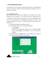
5.5 Data
The
Data
tab is used to display or download data. After sampling has been
completed, the
Data
tab is touched and the “Port 1 Data” screen is displayed. The
stored data includes: start time; stop time; average, minimum, and maximum flow
rate; collected volume; error status, and elapsed time.
NOTE:
The start time is when the sampling cycle starts. This includes 20 seconds
of leak check prior to allowing flow through the cartridge. The end time is when the
sampling cycle is completed after a thirty second leak check. Therefore, the total
time for flow through the cartridge is the end time minus the start time minus 50
seconds.
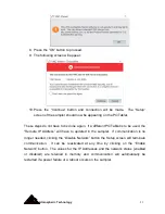
If the label printer option has been installed, a label can be printed for each port by
pressing the
Label
button. On each label the following information will be printed:
start date/time, end date/time, total sampled volume, average flow rate, and error
flag. The error flag is the sum valve of all errors that occurred during the sample
period. The error values are:
0
No Errors
2
Leak Check Flow Limit Exceeded
4
Temperature Tolerance Exceeded
16
Flow Rate Tolerance Exceeded
32
Flow Rate Zero Exceeded
64
Power Failure
128 Aborted
Содержание 8000
Страница 2: ......
Страница 4: ...ii Atmospheric Technology ...
Страница 8: ...2 Atmospheric Technology ...
Страница 14: ...8 Atmospheric Technology ...
Страница 18: ...12 Atmospheric Technology ...
Страница 30: ...24 Atmospheric Technology ...
Страница 39: ...Atmospheric Technology 33 Appendix A Schmatics ...
Страница 40: ...34 Atmospheric Technology ...
Страница 41: ...1 Model 2200V11 Interface Board Schematic 1 sch 7 ...
Страница 42: ......
Страница 43: ...Model 2200V11 Interface Board Schematic 2 sch 2 7 ...
Страница 44: ......
Страница 45: ...Model 2200V11 Interface Board Schematic 3 sch 3 7 ...
Страница 46: ......
Страница 47: ...Model 2200V11 Interface Board Schmatic 4 sch 4 7 ...
Страница 48: ......
Страница 49: ...Model 2200V11 Interface Board Schematic 5 sch 5 7 ...
Страница 50: ......
Страница 51: ...Model 2200V11 Interface Board Schematic 6 sch 6 7 ...
Страница 52: ......
Страница 53: ...Model 2200V11 Interface Board Schematic 7 sch 7 7 ...
Страница 54: ......
Страница 55: ...Atmospheric Technology 49 Appendix B Manual for Mass Flow Controller ...
Страница 56: ......