


Atmospheric Technology
9
4. Running the System
4.1 Hardware Setup
Upon arrival, check all shipping containers for damage and notify the shipper if
damage has occurred. Retain the shipping container because the sampler must be
returned in the original packaging if warranty repairs are required
.
Plug the main
power cord into a 115VAC outlet. Turn the main power on by using the power
switch on the rear of the sampler. When power is applied, the display will illuminate
in approximately 20 seconds.
The Model 8000 uses an WVGA LCD color touch screen display to show current
operating status and to enter information into the computer. The computer is
accessed using the tabs which are displayed on the screen and can be activated by
finger touch or stylus. A pencil eraser also works well. The touch level of the screen
can be calibrated by using the
TouchScreen
button in the
Setup
function.
A USB connector is mounted below the touchscreen. This can be used to connect a
mouse, keyboard, label printer, or jump drive for retrieving data and updating the
sampler software.
All components, tubing, and fittings have been cleaned prior to assembly. The
completed sampler has been purged with clean humidified air prior to shipment.
After unpacking the instrument and verifying operation, the Model 8000 should be
purged with humidified zero air for a minimum of 24 hours before sampling.
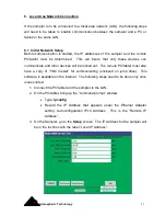
4.2 Display and Function Tabs
Normally the display will show the default main screen as illustrated here. This
screen displays current sampling information and provides function tabs for the
operator to enter operating parameters and retrieve data. The main screen displays
the following:
Содержание 8000
Страница 2: ......
Страница 4: ...ii Atmospheric Technology ...
Страница 8: ...2 Atmospheric Technology ...
Страница 14: ...8 Atmospheric Technology ...
Страница 18: ...12 Atmospheric Technology ...
Страница 30: ...24 Atmospheric Technology ...
Страница 39: ...Atmospheric Technology 33 Appendix A Schmatics ...
Страница 40: ...34 Atmospheric Technology ...
Страница 41: ...1 Model 2200V11 Interface Board Schematic 1 sch 7 ...
Страница 42: ......
Страница 43: ...Model 2200V11 Interface Board Schematic 2 sch 2 7 ...
Страница 44: ......
Страница 45: ...Model 2200V11 Interface Board Schematic 3 sch 3 7 ...
Страница 46: ......
Страница 47: ...Model 2200V11 Interface Board Schmatic 4 sch 4 7 ...
Страница 48: ......
Страница 49: ...Model 2200V11 Interface Board Schematic 5 sch 5 7 ...
Страница 50: ......
Страница 51: ...Model 2200V11 Interface Board Schematic 6 sch 6 7 ...
Страница 52: ......
Страница 53: ...Model 2200V11 Interface Board Schematic 7 sch 7 7 ...
Страница 54: ......
Страница 55: ...Atmospheric Technology 49 Appendix B Manual for Mass Flow Controller ...
Страница 56: ......