


GigaX Series L2 Managed Switch User’s Guide
104
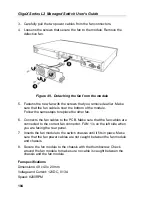
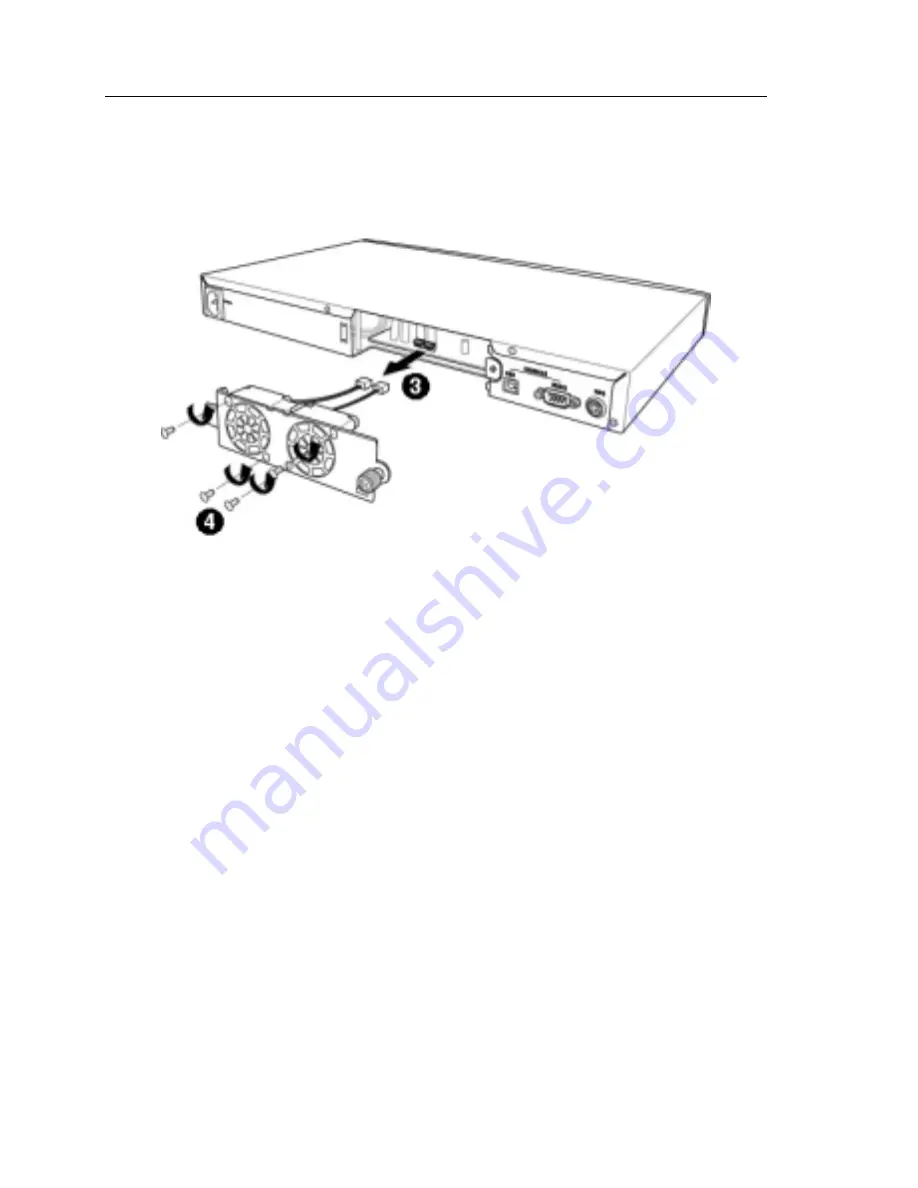
3. Carefully pull the two power cables from the fan connectors.
4. Loosens the screws that secure the fan to the module. Remove the
defective fan.
Figure 49. Detaching the fan from the module
5. Fastens the new fan with the screws that you removed earlier. Make
sure that the fan cable is near the bottom of the module.
Follow the same steps to replace the other fan.
6. Connects the fan cables to the PCB. Make sure that the fan cables are
connected to the correct fan connector. FAN 1 is on the left side when
you are facing the rear panel.
7. Inserts the fan module to the switch chassis until it fits in place. Make
sure that the fan power cables are not caught between the fan module
and chassis.
8. Secure the fan module to the chassis with the thumbscrew. Check
around the fan module to make sure no cable is caught between the
chassis and the fan module.
Fan specifications
Dimensions: 40 x 40 x 20 mm
Voltage and Current: 12VDC, 0.13A
Speed: 8200RPM
Содержание GigaX 2124X
Страница 1: ...GigaX Series Layer 2 Managed Switch User Guide ...
Страница 34: ...GigaX Series L2 Managed Switch User s Guide 34 Figure 15 Firmware Upgrade ...
Страница 36: ...GigaX Series L2 Managed Switch User s Guide 36 Figure 16 Physical Interface ...
Страница 45: ...GigaX Series L2 Managed Switch User Guide 45 Figure 23 Dynamic Address ...
Страница 48: ...GigaX Series L2 Managed Switch User s Guide 48 Figure 25 Tagged VLAN ...
Страница 57: ...GigaX Series L2 Managed Switch User Guide 57 Figure 33 USM User ...