ASUS RS300-E9 Series
4-3
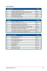
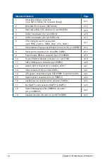
Layout contents
Jumpers
Page
1.
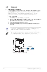
Clear RTC RAM (3-pin CLRTC1)
4-8
2.
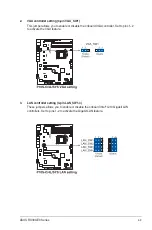
VGA controller setting (3-pin VGA_SW1)
4-9
3.
LAN controller setting (3-pin LAN_SW1-4)
7-6
4.
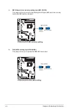
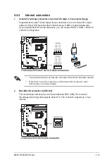
ME firmware force recovery setting (3-pin ME_RCVR1)
4-10
5.
PCH_MFG1 setting (3-pin PCH_MFG1)
4-10
6.
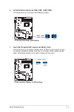
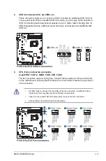
SATA DOM power setting (3-pin DOM1_PWR1, DOM2_PWR2)
4-11
7.
Smart Ride Through setting (3-pin SMART_PSU1)
4-11
Rear panel connectors
Page
1.
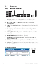
PS/2 keyboard/mouse port
4-12
2.
RJ-45 port for iKVM
4-12
3.
Video Graphics Adapter port
4-12
4.
RJ-45 ports for LAN
4-12
5.
Power-on Button
4-12
6.
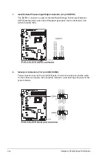
Message LED
4-12
7.
USB 2.0 ports 1 and 2
4-12
8.
USB 3.0 ports 1 and 2
4-12
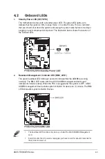
Onboard LEDs
Page
1.
Standby Power LED (SB_PWR1)
4-5
2.
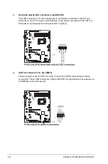
Baseboard Management Controller LED (BMC_LED1)
4-5
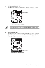
3.
CPU Warning LED (ERR_CPU1)
4-6
4.
Message LED (LOCLED1)
4-6
5.
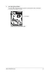
CATT ERR LED (CATTERR1)
4-7
Содержание 90SV038A-M34CE0
Страница 1: ...1U Rackmount Server RS300 E9 PS4 RS300 E9 RS4 User Guide ...
Страница 22: ...Chapter 1 Product Introduction 1 10 ...
Страница 48: ...Chapter 2 Hardware Information 2 26 ...
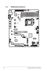
Страница 54: ...Chapter 4 Motherboard Information 4 2 4 1 Motherboard layout ...
Страница 97: ...5 19 ASUS RS300 E9 Series Intel Server Platform Services Intel TXT Information ...
Страница 146: ...6 18 Chapter 6 RAID Configuration ...
Страница 157: ...ASUS RS300 E9 Series 7 11 8 Press Restart Now to complete the setup process ...
Страница 163: ...Appendix A Appendix ...
Страница 164: ...A 2 Appendix P10S C 4L SYS block diagram ...
Страница 168: ...A 6 Appendix ...

