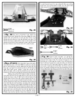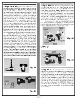
page 9
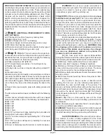
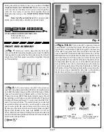
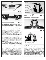
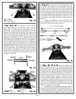
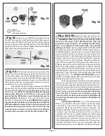
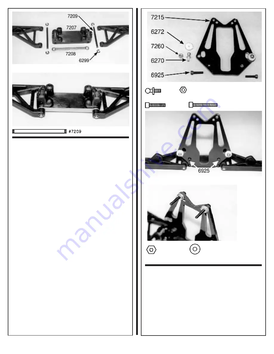
Fig. 15
Fig. 16
❏
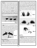
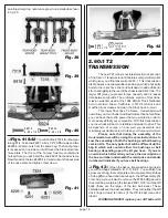
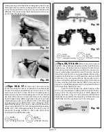
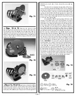
Figs. 17, 18 & 19
(1) From bag #6-14 remove
two #6270 short steel ball ends, two #7260 4-40 small pattern
thin plain nuts, and two of the #6272 foam ball end dust
covers. (2) Now take the #7215 black fiberglass front shock
strut and two #6925 4-40 x 1/2" SHCScrews from bag #7-1.
(3) Install the #6270 short ball ends in the two holes outside
of the small oval shaped holes as shown. At this time it does
not matter which side of the shock strut you use. Tighten the
ball ends (4) then install and tighten the two plain nuts on the
ball ends. (5)Install the dust covers over the balls now. (6)Go
back to your #6950 tool bag and take out the largest Allen
wrench (3/32"). (7) Use the two #6925 SHCScrews and the
3/32" Allen wrench to mount the #7215 shock strut on the
back side of the #7207 front bulkhead, making sure that the
ball ends are on the back side facing away from the bulkhead
(see fig. 15).
Note: All of the 4-40 SHCScrews in the kit can
be installed with the 3/32" Allen wrench supplied in the #6950
tool bag. But an Associated #6960 3/32" Allen driver (or an
equivalent brand) will make installation of the same screws
easier and quicker.
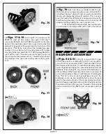
(8) Inside the master shock bag are bags #7-9, #7-
10, and the shock assembly parts bag. From the master
shock bag find and open bag #7-10 (the front shock bag). (9)
Open the miscellaneous hardware bag that is inside bag #7-
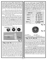
10 and remove two each #6927 4-40 x 3/4" SHCScrews,
#6295 4-40 plain nuts, and #6936 #4 aluminum flat washers.
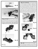
(10) Install and tighten the #6927 SHCScrews in the outer
hole at the top of the front shock strut (see fig. 19). Install the
screws from the back side so the screw heads are on the
same side as the ball ends. (11) Now place a flat washer over
the threads of each screw. (12)Next install and tighten a plain
nut onto the threads of each screw as shown (see fig. 16). If
everything is installed correctly the threads will be on the front
side of the shock strut extending over the front bulkhead.
#627 0
4-40
#7 26 0
4-40
th in p la in nu t
Fig. 17
# 69 25
4 -4 0 x 1 /2
# 69 27
4 -4 0 x 3 /4
Fig. 18
Fig. 19
# 62 95
4 -4 0 p la in nu t
#693 6
#4 flat was he r
alu m inum
❏
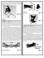
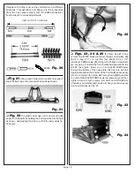
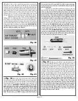
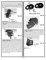
Fig. 20
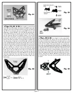
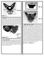
In bag #6-14 you will find fourteen #6274
plastic ball cups on a molded tree. In bag #7-1 you will find two
#7253 2.62" long turnbuckles; remove four of the ball cups
and thread them onto the turnbuckles evenly until you adjust
them to the 2 15/16" (2.94" or 74.60mm) dimension shown
below. We have also included a scale drawing of the
turnbuckle parts and assembly with ball cups installed.
THESE DIMENSIONS ARE TO THE
CENTER OF EACH
BALL CUP, NOT TO THE
END OF EACH BALL CUP. The
ball cups face the same direction when installed. The
turnbuckles have right hand threads on one end and left hand


