page 25
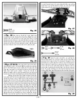
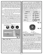
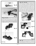
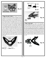
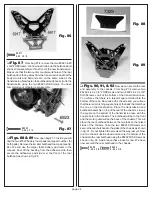
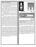
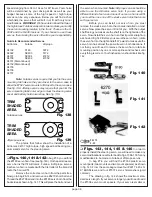
Fig. 90
Fig. 91
Fig. 92
❏
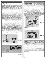
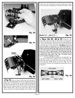
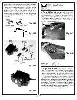
Fig. 93
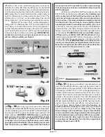
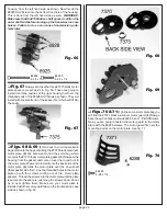
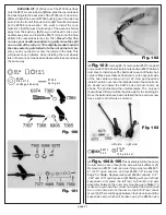
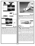
Now go to bag F of the Assoc. transmission.
Inside you will find two #6292 4-40 x 3/8" FHSScrews and two
#6291 4-40 x 1/4" FHSScrews. Use the two #6292 FHSScrews
to bolt the transmission to the chassis using the holes shown.
Make sure not to tighten these screws just yet. Now use the
#6291 FHSScrews to fasten the rear motor guard to the
chassis as shown. Go ahead and tighten all four screws. Now
that we have the transmission and motor guard secured we
can now go back and tighten all of the screws in figs. 91 & 92.
#62 92
4-40 x 3 /8
# 62 91
4 -4 0 x 1 /4
Fig. 93
❏
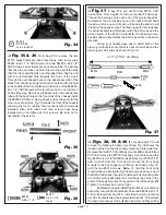
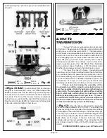
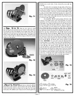
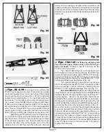
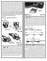
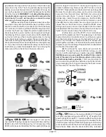
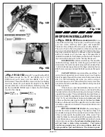
Figs. 94, 95, 96 & 97
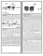
Go back to the
suspension arm bag and remove the #7354 rear suspension
arms. Fig. 94 shows you which arm is left and right and where
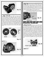
to remove the arms from the part mold runners. Fig. 95 shows
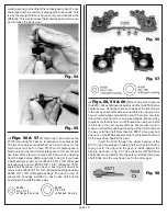
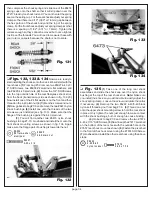
you which side is top and bottom.
WARNING!! It is very
important that you make sure you can tell the difference
between the top and bottom sides of the rear suspension
arms. It the arms are installed upside down the axles will
rub on the arms, causing wear and possible damage.
The bottom side of the suspension arm will be the same
height all the way across. the cross "X" portion on the
top side will be slightly recessed.
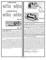
Now open bag #7-8 and remove the two #7657 rear
arm shock mounts and four #6925 4-40 x 1/2" SHCScrews.
Referring to fig. 97, secure the rear arm shock mounts to the
arms using the #6925 screws as shown. Make sure the
angled side of the mount is towards the inside of the arm and
angling out.
Fig. 94

