background image

page 14

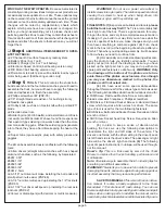
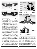
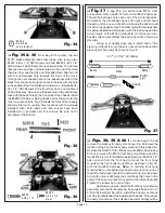
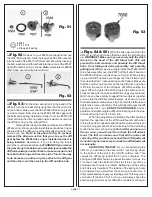
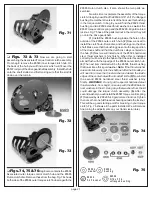
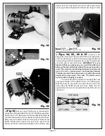
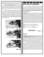
pointing straight up, not at an angle, when installed as shown
in fig. 40.

Fig. 38

 Fig. 39

# 6918
4 -40 x 1 /2

#69 24
4-40 x 3 /8

   Fig. 40

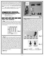
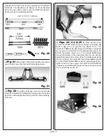
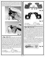
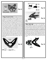
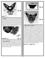
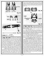
 Figs. 41 & 42

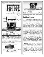
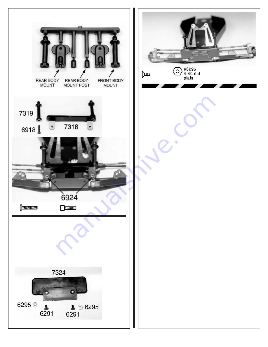
 You will find the #7324 front bumper

in bag #7-4. Take two #6291 4-40 x 1/4" FHSScrews and two
#6295 4-40 plain nuts from the same bag. The front bumper
is recessed on one side so it will fit over the black aluminum
nose plate. The front of the bumper has two countersunk
holes where you will install the two #6291 flat head screws.
Now thread on the two #6295 4-40 plain nuts on the back side
of the nose plate and tighten them down.

 Fig. 41

# 62 91
4 -4 0  x   1 /4

Fig. 42

2.60:1 T2 

TRANSMISSION

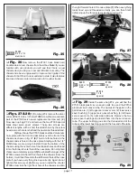
The new T2 Tranny is our latest electric truck version

of the Assoc. Transmission and features a larger differential
which gives you a final drive ratio of 2.60:1. This transmission
also features a new low profile case design, which physically
bolts to the rear shock strut and bulkhead to add additional
structural rigidity to the rear of the chassis and drive train. The
larger diff gives you greater torque capacity and increases
time between rebuilds. The prototype version of this trans-
mission was first used at the 1994 ROAR Truck Nationals
held in Garden Grove, California. It TQ'd both stock and
modified truck classes and won the Stock truck A-main.

This lower final drive T2 Assoc.  transmission will

now allow you to run hotter modified motors than before. Now
you can have that extra power that you wanted in order to
more easily defeat your competition. With this transmission
your new truck will be more reliable and easier to drive. This
all depends, of course, on how well you assemble and
maintain your transmission. So take your time and do it well.

Please note that during the assembly of the

transmission we will be using the same instructions to
sow the assembly of both the bushing and ball bearing
version kits. The only parts that will be different will be
bag B which will contain either the bushings or ball
bearings depending upon the kit you have.  If you are
uncertain which kit version you have, the description on
the box end label underneath the retail price and model
number will indicate if you have ball bearings.

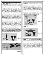
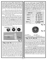
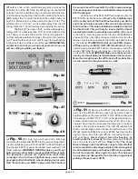
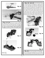
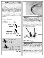
 Fig. 43

(1) Open the Assoc. transmission bag; inside

you will find bags marked A, B, C, D, E & F. You will also find
a gear cover bag, the motor plate and a couple of small tubes
of lube. (2) Go ahead and locate bag A, the diff assembly. (3)
From bag A you will want to remove the #7664 diff gear and
the small bag containing the twelve #6581 3/32" carbide diff
balls (these are the larger of the two ball sizes). These
carbide balls are the best available. They will outlast the diff
drive rings at least ten times (if the diff is kept clean and
lubed).

WARNING! NEVER replace your diff balls with

Содержание RC10T2

Страница 1: ...r ances To put the power to the ground this version also includes some of the same tires we race with The Proline XTR compound Edge front tires and Mini Pin rear tires with front and rear foam inserts for improved steering and traction You still get our race proven hard anodized PTFE coated shocks and PTFE shock pistons Associated Torque Control transmission clutch and one piece racing wheels To c...

Страница 2: ...ed builders and racers please build the truck our way first The T2 is a remarkably fast truck right out of the box There s a good reason for every thing on the truck and very few compromises were made in its design If you build it our way first you can see what the truck is capable of before you make changes and you will then have something to compare against 2 Put a check mark in the box at the b...

Страница 3: ...ront carrier blocks The carrier blocks are connected by a small molded runner which you will need to remove with your X acto knife Be sure to remove all of the runner 4 Screw one of the ball ends into each carrier block as shown 5 and then thread on the plain nuts NOTE A 3 16 nut driver SP 86 will make installing the steel ball ends and small4 40nutseasier 6 Nowinstalloneofthefoamballend dust cove...

Страница 4: ...ock step 2 making sure that the hole in each axle lines up with the hole in the steering block The parts should push together with your fingers if they do not then you may fit a 1 4 nut driver over the threaded end of the axle and then push the axle into the steering block step 3 WARNING The threads on the end of the axle are aluminum and can easily be damaged by the nut driver When installed the ...

Страница 5: ...ge pin 6 Install a 6299 1 8 E clip on each end of the hinge pin The ball ends will both be on the back or straight side of the A arm when installed correctly The 6210 block carrier will be angled towards the front as shown in fig 13 6 Now repeat the above steps for the right side A arm It will be a mirror image of the left Fig 11 6299 e clip 1 8 shaft Fig 12 Fig 13 Figs 14 15 16 Go back to bag 7 1...

Страница 6: ...the master shock bag find and open bag 7 10 the front shock bag 9 Open the miscellaneous hardware bag that is inside bag 7 10 and remove two each 6927 4 40 x 3 4 SHCScrews 6295 4 40 plain nuts and 6936 4 aluminum flat washers 10 Install and tighten the 6927 SHCScrews in the outer hole at the top of the front shock strut see fig 19 Install the screws from the back side so the screw heads are on the...

Страница 7: ...l cup off of the ball end as fig 22 shows Fig 22 Figs 23 24 25 1 Open bag 7 4 and remove the 7305 black aluminum chassis nose plate 2 Back in bag 7 1 you will find four 6280 8 32 x 1 2 aluminum FHMScrews 3 Using a 2 Phillips screwdriver we are going to install the front bulkhead assembly to the 7305 nose plate Insert one of the 6280 FHMScrews through the bottom of the nose plate and line it up wit...

Страница 8: ...nstall it from the bottom of the chassis using the center hole of the chassis holes and thread it into the forward center hole of the nose plate Do not tighten this screw completely just yet 5 Nowinstallthelongerofthe 7306 screws into the left front hole of the chassis from the bottom Itwillthenthreadintotheleftforwardholeofthenose plate if you have everything lined up correctly Again do not tight...

Страница 9: ...ooseningthealuminumadjust ing nut This changes the tension on the servo saver spring The more you tighten the servo saver spring the more load you transfer to the servo gears The adjusting nut should only be below the initial setting under limited racing conditions on an extremely high traction surface Fig 30 Fig 31 Figs 32 33Now we need to go back to bag 6 14 and remove five 6270 short steel ball...

Страница 10: ... both right and left hand threads and on one end of each turnbuckle the ball cup will threadontheoppositeway Thedrawingswiththisstepshow the actual assembled dimension with the ball cups and the actual length of the 7253 turnbuckle On these two turn buckles when assembled the ball cups all face the same direction Using your needle nose pliers install both of the steering turnbuckles onto the servo...

Страница 11: ...his lower final drive T2 Assoc transmission will nowallowyoutorunhottermodifiedmotorsthanbefore Now you can have that extra power that you wanted in order to more easily defeat your competition With this transmission your new truck will be more reliable and easier to drive This all depends of course on how well you assemble and maintain your transmission So take your time and do it well Please not...

Страница 12: ...se a 6596 bushing for the torque clutch If you have a ball bearing kit you will have eight bearings and one bushing while the bushing kits will have nine bushings Note Allthebushingsusedinthekitarepre oiledthroughaspecial manufacturing process so no oil in needed on the bushings during the assembly In this bag you will find a total of eight bearings and one bushing 2 Remove one of the 6589 5 32 x ...

Страница 13: ... center hole of the first thrust washer you will be see that each side is beveled One side is beveled more than the other This side is installed towards the head of the thrust bolt This will help to insure that the thrust assembly will work as smoothly as possible 3 Go back to the Assoc main bag and locate the tube of 6588 black grease 4 Open the tube and place a small amount on the washer Use jus...

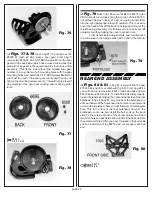
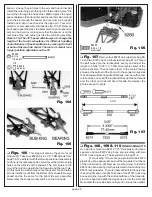
Страница 14: ...ve hub assembly over the 6575 diff bolt until it seats on the 7666 diff drive ring as shown in fig 54 When picking up your left diff hub place your finger over the slotted end of thehubsothattheT nutandspringcannotfallout Makesure that the outdrive hub centers on the top diff drive ring when it fits into the center of the diff gear 3 While holding the upper diff hub tighten the diff bolt using the...

Страница 15: ...lled in each case half but the bushings will install the same way 6906 3 8 x 3 16 unflanged bearing 6903 3 8 x 5 8 unflanged bearing Fig 56 Fig 57 Figs 58 59 60 1 Open bag D and remove the 6571driveshaft gearassemblyandthetwo 7669drive shaft spacers Carefully check both sides of the roll pin hole inthedrivegear shaftandmakesuretherearenoburrsinthe hole or raised edges around the hole If there are ...

Страница 16: ...2 now pick up your differential assembly so we can install it into the lower bearing of your transmission case Note Make sure that you install the diff bolt head so that it will end up on the same right passenger side of the transmission where the drive shaft is If you install the diff backwards so that it is on the left or driver s side you may have a problem with the diff backing off loosening u...

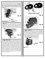
Страница 17: ...e set aside in Fig 56 These are going to install into three cavities of the right housing half over the threaded ends of the 6928 SHCSrews as shown They will install with the small end of the spacer first which will fit into the cavity Fig 67 Figs 68 69 1 Go back to your transmission bag and locate the bag containing the 7370 black aluminum motor plate 2 We also want to find the small bag which co...

Страница 18: ...ulon disc and bushing onto the drive shaft Make sure that the bushing goes onto the large portion of the drive shaft and that the clutch disc stays centered on the hub 3 Next we will install one of the 6594 hardened steel thrust washers shiny finish When this is installed correctly it will be inside the hub so that the outer face will be almost flush with the top edge of the 6584 outer clutch hub ...

Страница 19: ...iff bolt and to help keep dirt out of the thrust bearing assembly It still allows you to check your diff adjustment without taking the cover out each time Final transmission adjustments and maintenance are discussed in the tuning section at the end of the manual Fig 79 REAR END ASSEMBLY Figs 80 81 In bag 7 4 you will find the new 7322 black nylon rear bulkhead fig 80 From bag 6 14 you will need to...

Страница 20: ... the mount fits into the bottom hole of the shock strut and the body mount is facing up This side will now be thebackoftheshockstrut Threadthe 6924screwsthrough the center holes from the front side as shown in fig 84 Go ahead and attach the second mount on the other side of the shock strut Fig 82 6285 4 40 x 1 4 steel 6924 4 40 x 3 8 Fig 83 Fig 84 Figs 85 86 From bag 7 4 remove two 6917 4 40 x 3 8...

Страница 21: ... secure the rear end assembly to the chassis From bag 7 4 remove two 6292 4 40 x 3 8 FHSScrews and two 6924 4 40 x 3 8 SHCScrews Look at the bottom of the transmission case You will see that there is a raised square molded into the bottom of the case Now look at the chassis and you will see that there is a matching square hole at the back that matches the one on the transmission Place the transmis...

Страница 22: ...354 rear suspension arms Fig 94 shows you which arm is left and right and where toremovethearmsfromthepartmoldrunners Fig 95shows you which side is top and bottom WARNING It is very important that you make sure you can tell the difference betweenthetopandbottomsidesoftherearsuspension arms It the arms are installed upside down the axles will rub on the arms causing wear and possible damage The bot...

Страница 23: ... depending upon which version of the T2 that you have purchased Go back to bag 7 8 and remove the 7365 0 rear hub carriers IfyouhaveaballbearingT2youwillalsoremovetwo 7377 aluminum rear axle bearing spacers two 7367 new universal dogbone rear axles twelve 7368 3 16 rear axle shims 14 in the bag two 7369 1 16 rear axle spring pins and the small bag containing the four 6906 3 16 x 3 8 unflanged ball...

Страница 24: ...73 long ball ends two 72604 40smallplainnutsandtwo 6272ballend dustcovers Installoneoftheballendsoneachofthetwohub carriers Make sure that each ball end is on the opposite side of the hub carrier as shown in fig 103 Now go ahead and install the plain nuts onto the threaded end of each ball end Go ahead and install the 6272 ball end dust covers as shown The photos show the universal axles The only ...

Страница 25: ...nnot be used Thread the two screwsintothemountfromthebottomofthechassis Nowgo ahead and do the same for the right side arm assembly Remember the shock mounts will be on the front side 6280 8 32 x 1 2 aluminum Fig 106 Fig 107Remove four 6274 ball cups from bag 6 14 and two 7253 truck turnbuckles from bag 7 8 Thread the ball cups onto the turnbuckles evenly and adjust the length to 3 3 64 3 05 or 77...

Страница 26: ...REFULLY Fig 111 In the kit bag you will find the new master shock bag which contains bags 7 9 7 10 the shock piston bag and the shock assembly parts bag We have found it easier to assemble all four shocks at the same time 1 Open bag 7 9 and remove the two 6458 rear shock shafts 2 Now open bag 7 10 and remove the two 6459 front shock shafts 3 Next open the shock assembly parts bag Inside you will f...

Страница 27: ...IN IT IS SAFER TO REMOVE A TINY AMOUNT OF THE PART WHERE THE MOLD RUNNER WAS AT TACHED This applies to both the small nylon washers and the large nylon spacers Any part of the mold runner remaining will prevent the parts from snapping in cor rectly This will cause leaking around the shock shaft can cause binding of the shock shaft and reduce the shocks performance Use your finger on the edge of th...

Страница 28: ...ed tip on the assembly tool will be almost flush with the bottom of the shock body as shown on the right side of fig 121 9 Nowstandtheshocktoolonyourworkbenchwith the shock body on top Push down firmly on the shock body We want to hear and feel the split washer snap ito its groove The split washer is made of a hard material so it might take quite a bit of pressure before it will snap into place Th...

Страница 29: ...6 127 128 Now we need to remove the shock caps If you have a bushing kit you will find two 6428 black plastic shock caps in bag 7 9 and two more in bag 7 10 If you have a ball bearing kit there will be two 6439 black aluminum shock caps in bag 7 9 and two more in bag 7 10 Now we can fill each shock with shock oil 1 Take your container of silicone 25 weight shock oil and fill one shock body until i...

Страница 30: ...ing cup parts from the parts trees 4 Slide the nylon spring clamp onto each shock To make it easier to adjust the springs later install the spring clamps so that the 6932 screws will be on the outside and facing forward on each shock 5 Each spring clamp has one open hole and one closed hole for the tension screw Install the 6932 screw through each open hole and then thread it into the closed hole ...

Страница 31: ... bushings 6 Install one onto the threads of the two screws we just installed see fig 133 Make sure that the flange of the bushing is against the 4 40 plain nut 7 You will find another two 6473 nylon shock bushings in bag 7 10 Go ahead and install them onto the front shock mounting screws as shown in fig 134 Again make sure the flange part of bushing is towards the nut 6936 4 flat washer aluminum 6...

Страница 32: ...hocks installed onto the truck We have now completed the chassis assem bly Fig 137 STEERING SERVO SECTION We are now ready to install the steering servo If you have not purchased a radio yet we recommend that you stay with a name brand company like Airtronics Futaba or JRpropo However it may be possible to use many other radios including some stick models This is something we recommend you determi...

Страница 33: ...orn will fit Remove the correct servo horn from the parts tree Now go to bag 6 14 and remove one 6270 short ball end Thread the 6270 ball end into the 9180 servo horn from the backsideasshowninfig 141 Thiswillplacetheballendover the servo when mounted Note KOpropo servos should be able to use the Airtronics servo horn If you are using a different brand of servo and none of our servo horns will fit...

Страница 34: ...ear screw as shown in fig 147 Line up the screws with the holes on the bottom of the 7336 plastic servo mounts and thread them into the mounts Your installed servo will look like fig 148 Fig 147 Fig 148 6292 4 40 x 3 8 6466 spacer 1 16 Figs 149 150 In bag 7 2 you will find one 6262 1 65 turnbuckle In bag 6 14 you will find the two remaining 6274 plastic ball cups Evenly thread the ball cups onto t...

Страница 35: ...and two 6936 4 aluminum flat wash ers CAPACITORS Werecommendtheuseofthree 1uf micro farad capacitors on all motors used in our bushing kits Wesupplythreewiththestockmotorthatcomesinthese kits For the ball bearing kits since you will be using an electronic speed control follow the speed control manufac turers directions for quantities type and mounting locations for the capacitors If the motor you ...

Страница 36: ...rate small bag inside the kit bag FOR THE BUSHING KITS the same parts will be in the motor bag Install the motor into the motor opening from the left side so that the shaft and pinion gear will stick through the gearing opening in the motor plate Fasten the motor to the bottom motor mounting hole of the motor plate using the 6515 screw and 6936 washer as in fig 157 Now install the upper mounting s...

Страница 37: ...yappliestotheBUSH ING KITS If you have a BALL BEARING KIT you will NOT have a bag 6 13 You can skip forward in the manual to fig 175 Fig 162From your bushing kit you will need to locate and remove bag 6 13 This contains the parts to assemble our mechanical throttle control This is a race legal resistor style throttle control which has a nine step forward and a five step brake circuit THIS RESISTOR...

Страница 38: ...an extra 3721 screw and washer 2 Lookattheservohornsthatcameonorwithyour servo Fig 166 shows five of the more common servo horns used by the major manufacturers The ideal design for this application isthesmallroundservohornshowninthecenter of the photo The other servo horns will work but they do require trimming so they will not interfere with the wiper arm movement 3 Push the chosen servo horn ba...

Страница 39: ...hing is correct rotate the wiper arm so that it goes under the bypass tab The wiper arm is suppose to fit snuggly between the resistor and bypass tab If not you can either adjust the position of the resistor by raising the mounting brackets or you can bend the end of the bypass tab down so that it makes more contact with the wiper arm Fig 171 shows your throttle servo assembled Fig 169 Fig 170 Fig...

Страница 40: ...d Now connect the 6745 motor output plug to the motor plug that is soldered onto the motor Your mechanical throttle control is now assembled and installed We will check the setup and make any adjustments in the final adjustments section later in the manual Fig 175 Fig 176 Fig 177 Fig 178 FOR BALL BEARING KITS we are now going to install the electronic speed control If you have not decidedonaspeedc...

Страница 41: ...nd of the tube and the antenna wire This will prevent the antenna tube from pulling out during a race Racers Tip Keep the antenna tube as long as possible for radio range about 15 inches or so but not to the point where it could get caught in the wheels or some other else WARNING Do not cut the radio receiver antenna wire Cutting this wire could detune the receiver caus ing severe radio interferen...

Страница 42: ...betterandfaster Second useahighquality60 40rosin core solder Small diameter solder is easier to work with WARNING Do not use acid core solder Acid core solder will damage electrical components Use only ROSIN core solder for electrical connections Figs 185 186 187The first two drawings show the recommended wiring layout for both six and seven cellhandassembledbatterypacksusinganelectronicspeed cont...

Страница 43: ...rsolderingbatterypacks Youwillalsoneedtochoosewhat type of connector or pin system you want to use between the speed control and battery pack We show using the Reedy 652 power connector pins in the photos Figs 188 189 showbraidandpinlocationsforbothsidesofasixcellbattery pack Figs 190 190 show both sides of a seven cell battery pack Fig 188 Fig 189 Fig 190 Fig 191 Fig 192 Go ahead and place your b...

Страница 44: ...e tip has been inserted rotate the bracedownandoverthebatterypack Asthebraceisrotated down it will get tight and then free up as the lock properly engages Fig 195 Figs 196 197 To secure the battery brace you need to slide one side of the battery brace over one of the front battery mount screws then squeeze the front battery mount so that you can slide the other side over the second screw Now we ca...

Страница 45: ...them over the top of the rear bulkhead If you aregoingtohardwirethemotor solderthewiredirectlytothe motor slide the blue and red wires that go to the motor through the opening in the side of the rear bulkhead Now measure the motor lead wires and cut them to the correct length Makesureyouleavesomeslackinthewiresformotor adjustment Now go ahead and solder the wires to the motor Makesuretheredwireiss...

Страница 46: ...ap screws Racers Tip Before we install the rear tires onto the wheels we need to drill two holes about 1 8 in size into the middleofthewheelsortiretreadsothetirecanventilate This will make the tire s performance more consistent We will start by inserting the nylon inner sleeve into each of the rear tires Carefully center the inner sleeve Now we will start with the outer half of the rear wheel Pres...

Страница 47: ... mounted facing the other way you will have less steering For Bushing kits Take out the two 7840Y fluores cent yellow three piece front wheels two 7870 Block Ribbed front tires and the small bag that contains the four 6599 3 16 x 3 8 unflanged bushings WARNING The bushing bag is very small and is loose inside the tire wheelbag Beextremelycarefulwhenremovingthetires and wheels so that it does not g...

Страница 48: ... This prevents the darker color from ghosting through the lighter color So first mask the section to be painted white The next color you mask is the next darker color nearest white and so on PAINTING THE BODY Now that you have the body fitted it is time to paint it The truck body is made of Lexan polycar bonate and is painted on the inside There are two different ways to paint the body by either b...

Страница 49: ... the output shaft Now recheck and fine tune with your radio trim knob if necessary Secure the servo horn with its mounting screw Step 7 Are your wheels now pointed straight forward If not start by checking the alignment of the left upper servo saver arm It should be pointing straight across the chassis If not then adjust the length of the tie rod between the servo horn on the servo and the upper l...

Страница 50: ...A sticking brush could be caused by dirt or the brush braided wire getting caught or hung up on the brush holder Either of these can prevent the brush from being axle to slide in and out inside the brush holder so that it is making contact with the commutator at all times You can normally correct either problem by pulling the brush out of the brush holder a very small distance and then letting it ...

Страница 51: ...ith warm water and a mild dish soap Any other products will dry out the Lexan and make it easier for the body to crack page 54 recommended method is to connect the motor to an old battery pack and while the motor is running spray a motor cleanerdirectlyonthebrushcommutatorarea Runthemotor for approximately 15 seconds and apply the spray several times for 2 or 3 seconds Disconnect the motor and spr...

Страница 52: ...ng coming out of the corner Reducing the positive caster will decrease the amount of steering you have going into a corner and increase the amount of steering you have in the middle of the corner and exiting the same corner Associated makes positive caster blocks in increments of 5 starting at 5 and going through 30 Your RC10T2 truck comes with 30 caster front carrier blocks which is what we recom...

Страница 53: ...ion OPTIONAL ADJUSTMENT For extremely rough track setup Change the 3 rear mount to a 0 rear mount and change the 0 rear hub carrier to a 3 rear hub carrier Makes the truck a little easier to drive over the rougher track sections OPTIONS Rear suspension mounts 7364 0 toe in per side 6360 1 1 2 toe in per side 7363 3 toe in per side included in kit Rear hub carriers 7365 0 toe in per side included i...

Страница 54: ...me current passes through each one CHARGER A good quality automatic charger will last longer than an economy unit so please do not cut yourself short here by trying to save a couple of dollars Any good name brand charger will do the job correctly Associ ated recommends a peak detection charger as opposed tothetimercharger Timerchargersincreasethechanceof making a mistake when charging the battery ...

Страница 55: ...the track or fails to move forward when you attempt to accelerate push the throttle control on your trans mitter to the brake position immediately and attend to the truck A small rock can stall the gears and if the throttle is left in the on position the result can be a burned out motor or electronic speed control unit If you run your truck to the point where more than one cell in the pack is comp...

Отзывы: