page 30
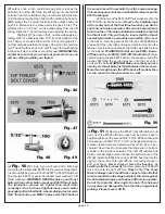
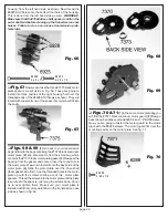
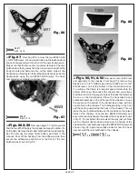
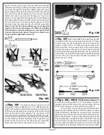
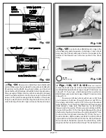
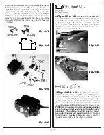
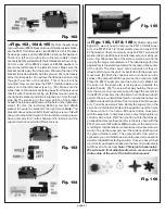
Fig. 112
right
wrong
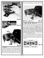
Fig. 113
❏
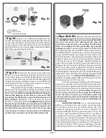
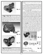
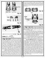
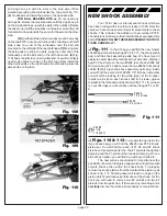
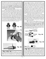
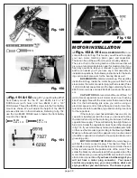
Figs. 114 & 115
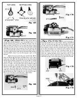
We are going to install the two
#6465 (#2) shock pistons on the two #6458 rear shock shafts
(the longer shafts). Secure each piston to the shaft with a
#6299 E-clip. Now we need to install the two #6465 (#3)
shock pistons onto the shorter front shock shafts and secure
them with an E-clip. Fig. 115 shows one shock shaft with
piston installed.
Racers Tip: It does not matter which way
you install the pistons, but we recommend having the number
up so you can see what piston you are using when you are
servicing your shocks.
Fig. 114 Fig 115
❏
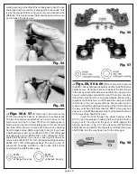
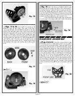
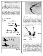
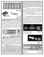
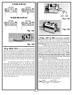
Figs. 116, 117 & 118
From the shock
assembly parts bag remove the #5407 red rings and the new
#6440 molded PTFE shock assembly parts. This molded
parts tree contains only enough plastic parts to assembly four
shocks, so take your time and don't damage or lose any.
Note:Part number #6440 is also a complete replacement set
of O-rings and plastic assembly parts to rebuild four shocks.
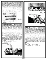
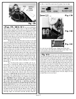
Fig. 116 gives the part names, as used in the instructions, for
each plastic part on the parts tree.
WARNING! Because of the precision tolerances
of these new parts, correct removal of the parts from the
parts tree is CRITICAL! Using an X-acto© knife with a
very sharp blade, carefully trim each part from the parts
tree. IT IS EXTREMELY IMPORTANT THAT NO PART OF
THE TWO MOLDING RUNNERS REMAIN. IF YOU ARE
UNCERTAIN, IT IS SAFER TO REMOVE A TINY AMOUNT
OF THE PART WHERE THE MOLD RUNNER WAS AT-
TACHED. This applies to both the small nylon washers
and the large nylon spacers. Any part of the mold runner
remaining will prevent the parts from snapping in cor-
rectly. This will cause leaking around the shock shaft,
can cause binding of the shock shaft, and reduce the
shocks performance. Use your finger on the edge of the
parts to feel for burrs that you cannot see and carefully
remove them.
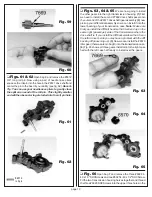
Fig. 117 shows a close up view of two small nylon
washers used with the red O-rings. The washer on the left still
has two small burrs on it while the one on the right side of the
photo has had all the burrs removed. The arrow in the photo
points to one burr and the second burr is directly opposite on
the other side of the same washer.
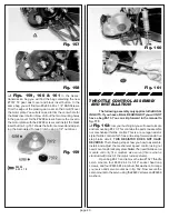
From the master shock bag remove the #6429 shock
assembly tool. Stand the assembly tool on end with the small
tip up.
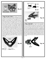
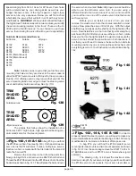
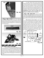
To correctly assemble each shock, install the parts
on the shock assembly tool in this order: (1) first the split
locking washer, (2) then one small nylon washer, (3) red O-
ring, (4) large nylon spacer, (5) second red O-ring, (6) and
second small nylon washer. You can compare this sequence
with layout in fig. 118. Fig. 122 shows a cutaway drawing of
the shock body with the internal seal parts installed.
Note: if
you need to replace just a red O-ring, you can purchase them
separately under part numbers #5407 (8 red O-rings).
Left: 4 large nylon spacers
Fig. 116
Center: 8 small nylon washers
Far right: 4 split washers
Fig. 117
# 540 7
re d O -rin g
Fig. 118

