page 40
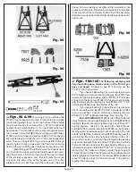
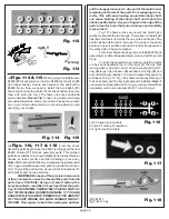
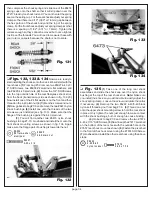
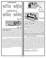
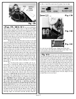
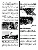
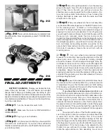
Fig. 157
Fig. 158
❏
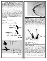
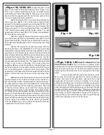
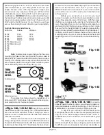
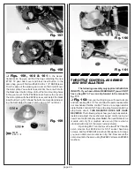
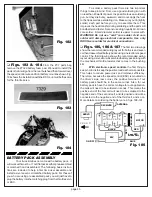
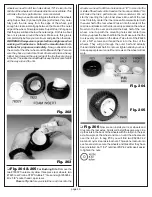
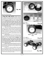
Figs. 159, 160 & 161
In the Assoc.
transmission bag you will find the bag containing the new
#7372 T2 gear dust cover and black insert button. In the
same bag you will find two #6288 4-40 x 1/4" BHSScrews.
Trim the edge of the plastic gear cover so that it will fit over
the motor plate. You will also need to trim the center hole for
the black insert button. Now drill out the two mounting holes
in the gear cover for the #6288 screws. Secure the cover to
the motor plate with the #6288 screws and install the black
insert button. Fig. 161 shows the button removed and adjust-
ing the Associated Torque Clutch using a 1/4" nut driver.
Fig. 159
# 62 88
4 -40 x 1 /4
Fig. 160
Fig. 161
THROTTLE CONTROL ASSEMBLY
AND INSTALLATION
The following assembly only applies to the BUSH-
ING KITS. If you have a BALL BEARING KIT you will NOT
have a bag #6-13. You can skip forward in the manual to
fig. 175
❏
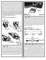
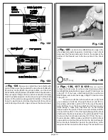
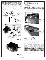
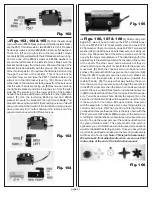
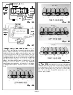
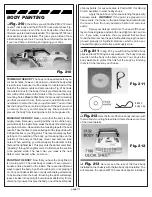
Fig. 162
From your bushing kit you will need to locate
and remove bag #6-13. This contains the parts to assemble
our mechanical throttle control. This is a race legal resistor
style throttle control which has a nine step forward and a five
step brake circuit. THIS RESISTOR DOES NOT HAVE
REVERSE. The following steps show you how to assemble,
install, and adjust the mechanical speed control using our
new mount and bracket system.
Note: The new throttle servo
mounts will only fit a medium size servo (this is what is
standard with most of the major radio systems).
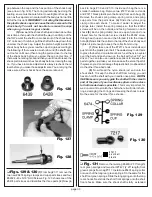
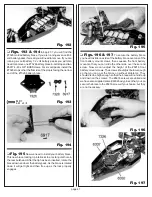
Open bag #6-13 and remove the two #7527 throttle
servo mounts, four #6932 4-40 x 5/16" socket head cap
screws, and four #6936 #4 aluminum flat washers. Arrange
your servo and servo mounts as in fig. 162. Now secure the
servo mounts to the servo using the #6932 screws and #6936
washers.

