10
An ASSA ABLOY Group brand
80-8420-0900 Rev. B (05-08)
SECTION
Troubleshooting
V
1. The Keypad does not beep or the lights do not blink when keys are pushed
2. The trim does not lock or unlock.
.
A. Check the keypad harness to ensure it is properly connected to the electronics board.
B. Ensure the batteries are properly installed and the “Remove Before Use” tag is removed.
C. Are the batteries dead?
D. Check the keypad harness for pinched or cut wires.
E (For hard wired option) Ensure the power supply is producing 9VDC.
This section is broken up into two areas. Area A is Electrical. Area B is Mechanical
A. Electrical
1. Can you hear the micro motor cycling in the trim? If yes refer to step B. If no follow the steps below.
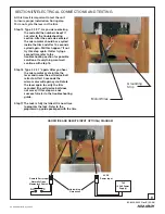
a. Check the motor harness to ensure it is properly connected to the electronics board.
b. Is the connector installed in the proper location on the board? There is a small label on the board MTR. This is
where the motor harness connects.
c. Ensure the batteries are properly installed and the “Remove Before Use” tag is removed.
d. Are the batteries dead?
e. Check the motor harness for pinched or cut wires.
f. (For hard wired option) Ensure the power supply is producing 9VDC.
B. Mechanical
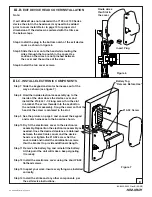
1. Ensure the Self-Adjusting Cap is properly centered in the receiving cam of the exit device.
2. Was a good quality metal door with the proper reinforcements used for this install? If not the device probably is not
working correctly because the door has “oil canned”. This means that when the through bolts were tightened it
caused the door to crush like an hour glass causing severe misalignment between the trim and the exit device.
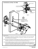
This problem may be corrected by loosening the pan head screws shown in figure 4. First try ½ turn (loosen) on
each of the pan heads. Try the lock again. If this does not fix the problem try another ½ turn. If this solves the
problem, ensure the surface applied screws provided are installed and tight.
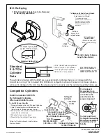
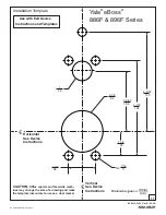
3. Another misalignment can be caused by a bad door prep. Ensure the door is properly prepped with the template
contained with these instructions and the template supplied with the exit device.
4. Finally, a third type of misalignment may be present. This is where the exit device has sagged on the door causing
the exit device to hang on the lockbody inside the trim causing internal misalignment. Loosen the exit device screws
and slightly lift the device while tightening the screws again.
If the above tips do not solve your problem please call our Technical Product Support Team at the phone number
listed on the back of these instructions.
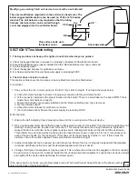
Modifying an existing Yale® exit devise to work with an exit eBoss®
The only modification required is to the exit device head cover. The
below suggested dimensions can be used on 7000 or 2100 series
devices. The slot below is only required so that the wiring
harness and lock wires can be routed through the
cover and plugged into the controller board.
9/16"
3/4"
3/8"
Door edge side
This surface butts up to
the battery cover.


