9
An ASSA ABLOY Group brand
80-8420-0900 Rev. B (05-08)
SECTION
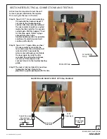
ELECTRICAL CONNECTIONS AND TESTING
IV
Grounding
Strip
Motor Wires
At this time it is important to test the unit
to insure proper installation. During step
15 do not cycle the lever or the trim.
Step 15 Type 4 3 2 1*. As you were entering
the code did the numbers beep? If
not refer to the troubleshooting
section. After the code was entered
the micro motor should have cycled
inside the trim and after 10 seconds
cycled again. Did this happen? If not
try this step again. If after trying a
second time refer to the
troubleshooting section for possible
solutions. If everything went well
continue with step 16.
Step 16 Type 4 3 2 1 * again. After you hear
the micro motor cycle rotate the
lever and insure the exit device bolt
retracts. After 10 seconds the
micro motor will again cycle. Rotate
the lever again to verify the trim
re-locked (the exit device bolt does
not move). If this step was not
successful refer to the troubleshooting
guide.
Step 17 The lock is fully installed. It is now time
to program the lock. Refer to the
programming guide packaged with the trim.
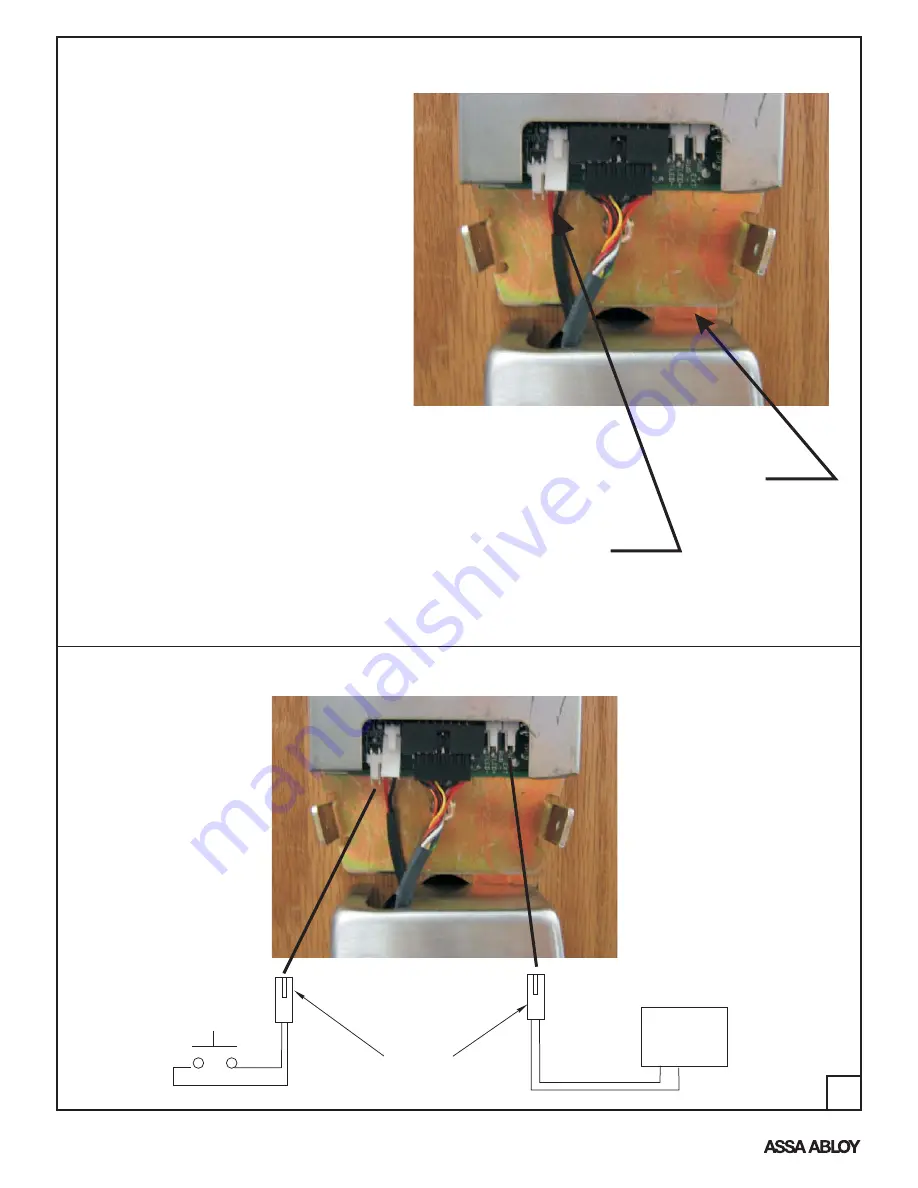
9VDC
Power input
784
(9 Volt Power
Supply)
Hardwiring
Harnesses
Normally Open
Momentary Switch
NO
C
HARDWIRE AND REMOTE INPUT OPTION(s) DIAGRAM
Remote Entry Input


