60
EN
Installation
Installing door fittings (according to DIN EN 179)
Warning!
Life-threatening danger and risk of injury resulting from incorrect installation of door handle fittings
according to with DIN EN 179:
Only escutcheons, lock counterparts, and coverings approved according
to DIN EN 179 may be used (“Door fitting in accordance with DIN EN 179”, page 70).
At tention!
Property damage after drilling through the lock:
The lock is damaged by drilling. You may only use exist-
ing holes drilled at the factory to attach door fittings. The lock must be removed prior to drilling.
Damage caused by dirt:
The lock is damaged by dirt. Prior to installation, the lock pocket and all holes
must be cleaned (by blowing out or vacuuming).
Property damage due to forceful installation of the handle pin into the follower:
The door handle
spindle must be gently inserted into the spindle hub. No tools are needed.
The lock must be installed in the door so that the holes for the door fittings can
be marked (“Installing the lock”, page 55, “Accessories”, page 70).
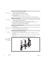
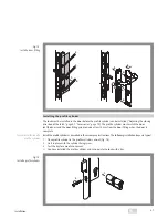
Install the door fittings as described in the accompany instructions. The following installation steps are
typical:
1
Insert the handle pin in the follower (Fig. 13 –
1
).
2
Mark the drilled holes (–
2
).
Normally, a drilling template accompanies the door fitting.
3
Remove the lock from the door.
4
Drill the holes.
5
Re-install the lock.
6
Install the door fittings on both side of the door (–
3
to –
6
).
7
Check the door handle for ease of movement.
You have installed the door fitting and can operate the lock with the door handle.
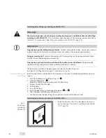
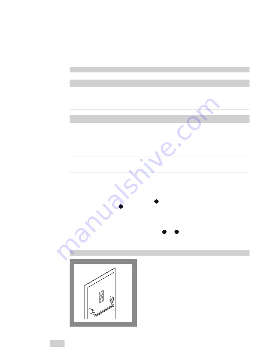
Installing door fittings (according to DIN EN 1125)
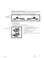
1 Install the panic bar (Fig. 12) as described in the accom-
pany instructions (“Panic bar in accordance with DIN EN
1125”, page 70).
!
A
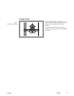
Typical installation of a
door fitting
Fig. 12 :
A panic door
according to
DIN EN 1125
Содержание OneSystem 519N
Страница 31: ...31 Technische Daten DE ...
Страница 49: ...49 Notes EN Fig 2 OneSystem motorised multi point lock 519N Fig 3 Rebate gap B A 2 3 4 5 6 7 8 9 1 ...
Страница 67: ...67 Technical data EN ...
Страница 103: ...103 Caractéristiques techniques FR ...
Страница 121: ...121 Indicazioni IT Fig 2 Serratura motorizzata multipunto 519N Fig 3 Luce di funzionamento B A 2 3 4 5 6 7 8 9 1 ...
Страница 139: ...139 Dati tecnici IT ...
Страница 157: ...157 Aanwijzingen NL Afb 2 OneSystem meervoudig vergrendelingsmotorslot 519N Afb 3 Sponningspeling B A 2 3 4 5 6 7 8 9 1 ...
Страница 175: ...175 Technische gegevens NL ...
Страница 187: ...187 Abmessungen Dimensions Dimensions Dimensioni Afmetins DE EN FR IT NL ...


