


92
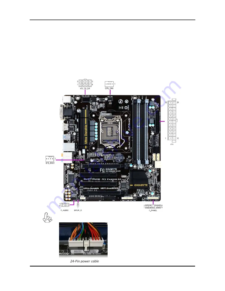
Connecting Case Components
After you have installed the motherboard into a case, you can begin connecting the motherboard components.
Refer to the following:
1. Connect the CPU cooling fan cable to
CPU_FAN
.
2. Connect the standard power supply connector to
ATX
3. Connect the auxiliary case power supply connector to
ATX_12V_2X4
.
4. Connect the system cooling fan connector to
SYS_FAN1
.
5. Connect the case switches and indicator LEDs to the
F_PANEL
.
Connecting 24-pin power cable
The ATX 24-pin connector Allow you to connect to ATX v2.x power supply.
With ATX v2.x power supply, users please note that when
installing 24-pin power cable, the latches of power cable
and the ATX match perfectly.
Содержание TC-651
Страница 13: ...7 Block Diagram...
Страница 28: ...22 Press F12 Key Boot Menu Page...
Страница 29: ...23 Press ALT F10 Key Copy Main BIOS to Backup BIOS Non Acer Recovery Function Page1 Page2...
Страница 32: ...26 Press F1 Key Page General Help...
Страница 33: ...27 Press F5 Key Page Previous Values...
Страница 34: ...28 Press F7 Key Page Optimized Default...
Страница 35: ...29 Press F9 Key Page System Information...
Страница 36: ...30 Press F10 Key Page Save Exit...
Страница 37: ...31 Press ESC Key Right Click Mouse Exit...
Страница 46: ...40 Page1...
Страница 50: ...44 Page...
Страница 64: ...58 2 Setting the Motherboard 2 1 Motherboard view 2 2 Install the CPU...
Страница 71: ...65 8 Install the front bezel 8 1 Install the bezel 8 2 Link the HDD LED power cable 9 Cable ties position...
Страница 72: ...66 10 Overview...
Страница 114: ...108...
Страница 115: ...109 FRU List The FRU list will be updated later...


