77
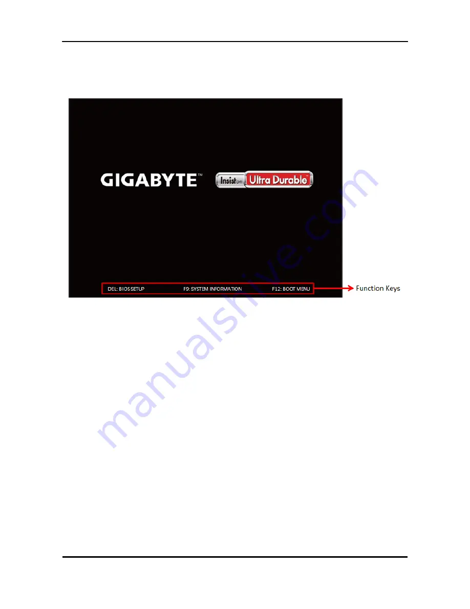
Power-On Self-Test (POST)
Each time you turn on the system, the Power-on Self Test (POST) is initiated. Several items are tested
during POST, but for the most part transparent to the user.
The Power-On Self Test (POST) is a BIOS procedure that boots the system, initializes and diagnoses the
system components, and controls the operation of the power-on password option. If POST discovers errors
in system operations at power-on, it displays error messages on screen, generates a check point
code at port 80h or even halts the system if the error is fatal.
The main components on the main board that must be diagnosed and/or initialized by POST to ensure
system functionality are as follows:
Microprocessor with built-in numeric co-processor and cache memory subsystem
Direct Memory Access (DMA) controller
Interrupt system
Three programmable timers
ROM subsystem
RAM subsystem
CMOS RAM subsystem and real time clock/calendar with battery backup
Onboard parallel interface controller
Embedded hard disk interface and one diskette drive interface
Keyboard and auxiliary device controllers
I/O ports
One PS/2-compatible all in one Keyboard/mouse port
NOTE: When Post executes a task, it uses a series of preset numbers called check points to be latched
at port 80h, indicating the stages it is currently running. This latch can be read and shown on a debug
board.
The following table describes the BIOS common tasks carried out by POST. Each task is denoted by an
unique check point number. For other unique check point numbers that are not listed in the table, refer to
the corresponding product service guide.
Post Checkpoints List: The list may vary accordingly depending on your BIOS
Содержание TC-651
Страница 13: ...7 Block Diagram...
Страница 28: ...22 Press F12 Key Boot Menu Page...
Страница 29: ...23 Press ALT F10 Key Copy Main BIOS to Backup BIOS Non Acer Recovery Function Page1 Page2...
Страница 32: ...26 Press F1 Key Page General Help...
Страница 33: ...27 Press F5 Key Page Previous Values...
Страница 34: ...28 Press F7 Key Page Optimized Default...
Страница 35: ...29 Press F9 Key Page System Information...
Страница 36: ...30 Press F10 Key Page Save Exit...
Страница 37: ...31 Press ESC Key Right Click Mouse Exit...
Страница 46: ...40 Page1...
Страница 50: ...44 Page...
Страница 64: ...58 2 Setting the Motherboard 2 1 Motherboard view 2 2 Install the CPU...
Страница 71: ...65 8 Install the front bezel 8 1 Install the bezel 8 2 Link the HDD LED power cable 9 Cable ties position...
Страница 72: ...66 10 Overview...
Страница 114: ...108...
Страница 115: ...109 FRU List The FRU list will be updated later...