* Note that the
selected relay will
remain closed if
another setpoint is
configured to use it
and if it is tripped.
3--16 Initial Set up
KW Setpoint Configuration
The
Power Manager Xp
provides the user with a dedicated programmable
setpoint based on Watt Demand. With this setpoint function, the user can
program the Power Manager to control one of the four built–in relays. When
the watt demand register exceeds the SP–KWDemand Hi setting, the
selected relay closes, and stays closed until the Watt Demand register falls
below the SP–KWDemand Lo setting for a preset amount of time
determined by the SP–Reset TD setting, upon which the relay opens (or
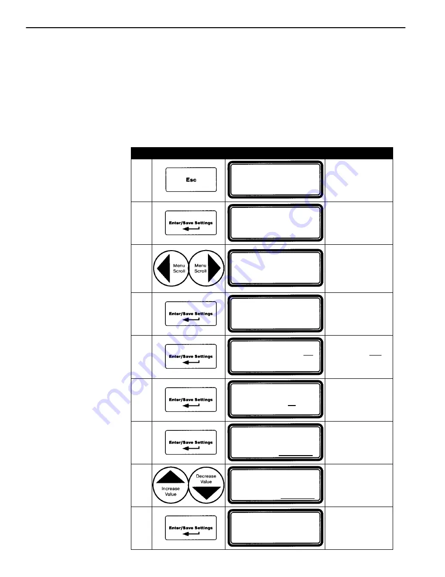
releases).* Select the output relay to be used for the setpoint function
(choices include, DO1, DO2, DO3, DO4, or NOT USED) as follows:
Step
Press
Display Shows
Comment
1
POWER SYSTEM TOTAL
404 KW
+1.00 PF
0 KVAR
60.00 Hz
404 KVA ATS
o
n NORM
Brings you to
top level if not
already there.
2
<<< SETTINGS >>>
System: 3
f
–4W WYE
Source: LOAD
KW Capacity:
0 KW
3
<<< SETTINGS >>>
Clear Max Demand? NO
Window Size:
15 min.
SP–Output:
Not Used
Press left & right
arrow keys until
the
Clear Max
Demand
location
appears.
4
<<< SETTINGS >>>
Enter password
0000
Enter password
as explained in
steps 5 & 6 on
page 3–1.
5
<<< SETTINGS >>>
Clear Max Demand?
NO
Window Size:
15 min.
SP–Output:
NOT USED
The word NO
is blinking.
6
<<< SETTINGS >>>
Clear Max Demand? NO
Window Size:
15
min.
SP–Output:
NOT USED
Window Size
is blinking.
7
<<< SETTINGS >>>
Clear Max Demand? NO
Window Size:
15 min.
SP–Output:
NOT USED
SP–Output
is blinking.
8
<<< SETTINGS >>>
Clear Max Demand? NO
Window Size:
15 min.
SP–Output:
NOT USED
Press up & down
arrow keys until
correct output
relay is displayed.
9
<<< SETTINGS >>>
Clear Max Demand? NO
Window Size:
15 min.
SP–Output:
NOT USED
Saves the new
setting. Nothing
is blinking.
Now press the
Esc
key to return to the top level display.


