


2--4
Installation
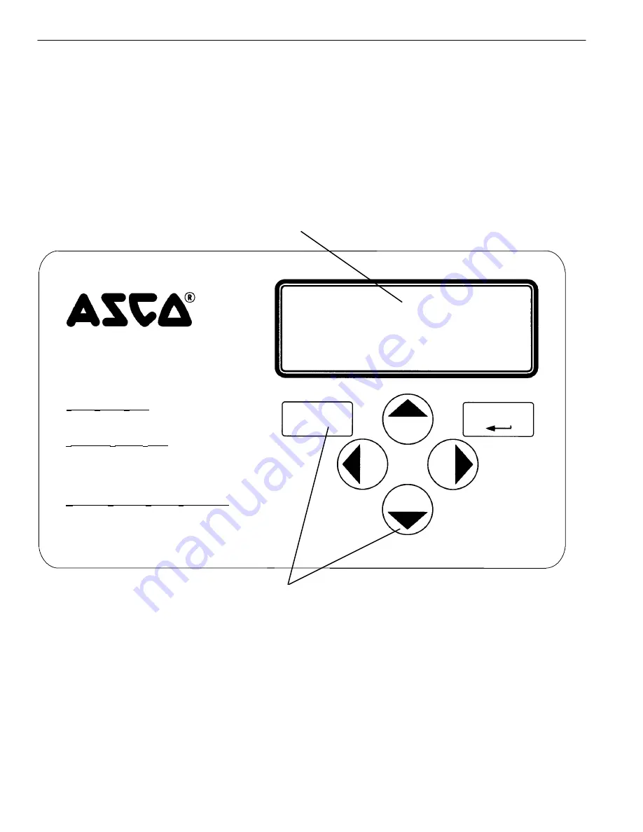
Control Overview
On the Catalog 5220D Power Manager Xp, which includes the display, six
control buttons perform all monitoring and setting functions. Three levels
of screens are used. The first (top) level is the
monitoring level
and provides
information about the power system. The second (middle) level is the
settings level
. Access to change the settings is password protected (see page
3–1). The third (lower) level is the
setpoints
level. There are twelve
user–configurable setpoints for protective relaying, containing two screens
per setpoint for parameter selection. A user may configure any combination
of these twelve setpoints, including duplicates. Acess to these screens is also
password protected (see page 3–1).
4–line LCD display
membrane control keys
P
OWER
M
ANAGER
P
OWER
S
TATUS
L
EVEL:
S
ETTINGS &
S
ERVICE
L
EVEL:
M
ODIFYING
S
ETUP OR
S
ERVICE
P
ARAMETERS:
Refer to Operator’s Manual
Press left or right
Menu Scroll
to display power
parameter screens.
Press
Enter/Save Settings
to display the
settings and service screens.
Press left or right
Menu Scroll
to display
settings or service screens.
Press
Esc
to return to the power status level.
E
sc
Enter / Save Settings
Increase
Value
Decrease
Value
Menu
Scroll
Menu
Scroll
Power Manager Display.
Left–Right Arrows
The left arrow
A
and right arrow
"
keys (
Menu Scroll
) navigate through
both levels of screens.
Enter/Save Settings
The
Enter / Save Settings
key drops from the top level to the lower level
settings screens. It also is used to save a new settings.
Up–Down Arrows
The up arrow
Y
and down
B
arrow keys (
Increase Value
and
Decrease Val-
ue
) modifies a setting (setup parameter) while in the lower level screens.
Esc key
The Esc key ignores a change and returns to the top level.


