


39
This option is only recommended when there is no internet connection available or when the
destination area is really small. Take an overview picture with the AscTec Falcon 8.
1.
Fly the UAV central over your destination area so that it is completely displayed on the MGS.
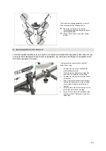
2.
Tilt the camera 90° down and take a picture.
3.
Land and transfer the image to a computer.
4.
Use any GPS device to measure prominent locations that are visible in the upper left and
lower right corner of the picture taken and note the coordinates.
5.
Crop the picture at the measured locations.
6.
Prepare the INI files as described (see
here
).
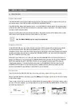
A GPS MISSION
GPS MISSION is another useful tool. Plan and execute semi-autonomous, waypoint based missions.
Load your own map images, manually or automatically generate waypoints and save your flight plan
for later action or reasons of documentation.
You even may FLY BY CLICK. Just click at a desired point on the map to reposition the UAV. With
GPS MISSION you are able to control a current mission directly in real time.
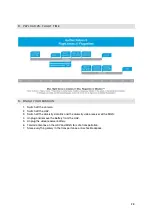
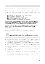
To perform a GPS Mission follow these steps:
1.
Importing a georeferenced image: Use GPS MISSION to open georeferenced images by
clicking on FILE
OPEN SATELLITE IMAGE. The related coordinates saved in the INI file will
be loaded automatically and assigned to that image.
2.
Generating a flight plan: You are able to add waypoints manually, set them systematically via
MATRIX EDITOR or save them during a flight together with its current orientation. Then you
may fly another time and take further pictures: from the same position, with the same camera
orientation.
3.
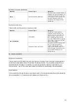
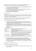
Waypoint Properties:
> DESIRED HEADING
Heading of the UAV at the waypoint. Possible parameters: 0° to 359°,
0° being North, 180° being south.
> HEIGHT
Defines the height above your starting point in meters.
> TIME @ WP
The vehicle will stay at the waypoint for the number of seconds given in this field before it will
continue to the next waypoint.
> POSITION ACCURACY
The vehicle has to be within a radius of e. g. 3 meters (= DEFAULT) to consider the waypoint
reached. After that, it will start to count the TIME @ WP. Please note that setting the position
accuracy to less than 3 meters might cause a long hovering time until a waypoint is
considered to be reached. Flying in high winds it makes sense to set 4 or even 5 meters.
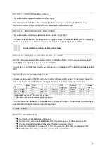
> TRIGGER CAMERA
If this box is checked, the AscTec Falcon 8 will take a photo when the waypoint is
considered reached, and half of the TIME @ WP has passed.
> SET CAMERA ANGLE
0° means the camera is pointing straight forward, 90° means the camera is pointing straight
down.
4.
Manually generating a flight plan: To add a waypoint manually you need to select
CURSORFUNCTION
ADD WAYPOINT. Click on the map on the desired waypoint and to
define the parameters in the WAYPOINT PROPERTIES window that opens automatically.
5.
To move an existing waypoint, select CURSORFUNCTION
EDIT WAYPOINT, right click on
the waypoint and move it.
GENERATING A MATRIX FLIGHT PLAN
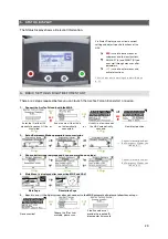
To generate a matrix flight plan follow these steps:
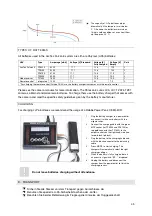
1.
Select CURSORFUNCTION
NONE and click the red cross on the map, where you want to
let your matrix start.


