background image

Chapter 1

General

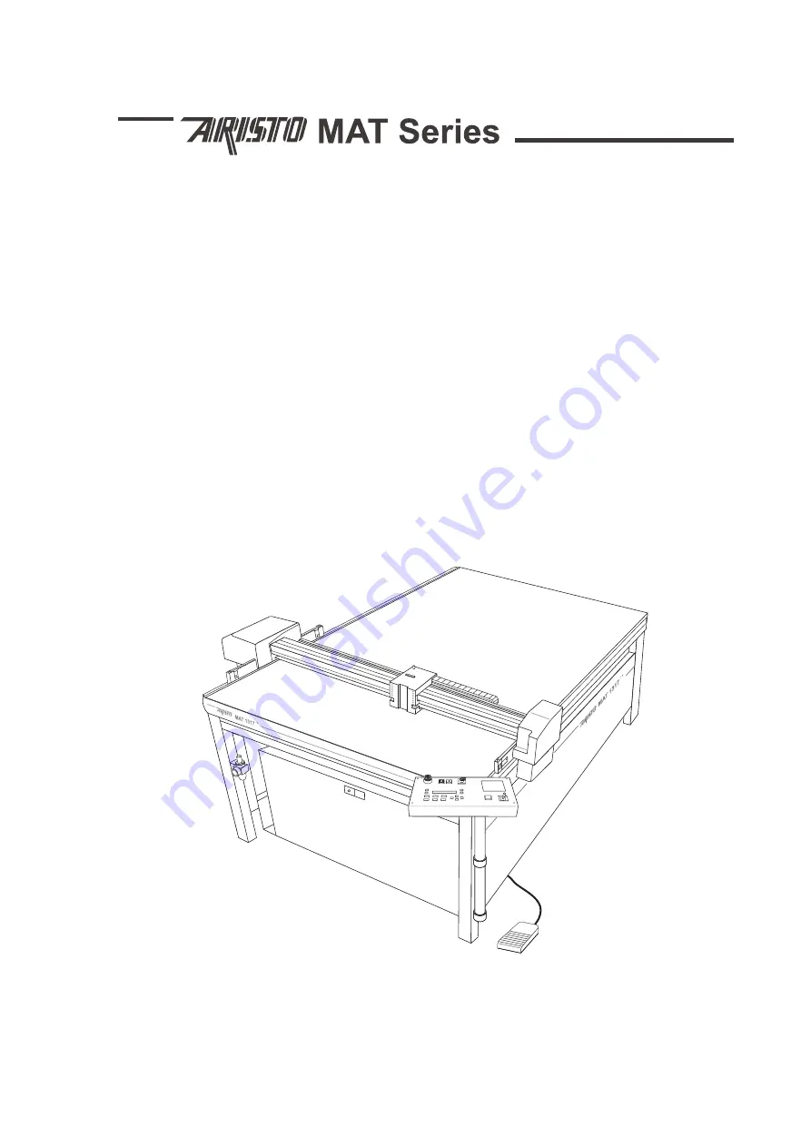
ARISTOMAT SL

131O/1317/1617/1625

Содержание ARISTOMAT SL 1310

Страница 1: ...Chapter 1 General ARISTOMAT SL 131O 1317 1617 1625 ...

Страница 2: ... writ ten permission of ARISTO Graphic Systeme ARISTO Graphic Systeme reserves the right to claim recourse in cases of violation ARISTO Graphic Systeme takes no manufacturer s responsibility for improper use of the hard and software This includes for exam ple interference with the hardware passing on of data to third par ties loss of data by erroneous erasure etc ARISTO Graphic Systeme GmbH Co KG ...

Страница 3: ...1 3 Contents Contents 1 Introduction 5 2 Safety Instructions 6 3 Safety Devices 9 4 Caution Areas 10 ARISTOMAT SL without Conveyor 10 ARISTOMAT SL with Conveyor 11 DECLARATION OF CONFORMITY 13 MANUFACTURER S DECLARATION 15 ...

Страница 4: ...1 4 ARISTOMAT SL Series Contents ...

Страница 5: ...STO reserves the right to make any alterations or improvements in the manual without any notice The complete documentation is partitioned into chapters Following parts belong to every ARISTOMAT Chapter 1 General Chapter 2 Basic Elements of the ARISTOMAT SL Chapter 3 Material Transport Systems Chapter 12 Light barrier and Collision Shut off Further chapters refer to the ARISTOMAT equipment you have...

Страница 6: ...nder supervision of experienced personnel only The faultless function of the safety devices must be checked before each operation With malfunctions the plotter shall not be taken in operation Covers are part of safety Do not remove any covers from the ARISTO MAT tool heads and accessories Unauthorized modification which might impair the safety of the machine are not permitted Safety Devices Light ...

Страница 7: ...ower maintain a sufficient safety distance no less than 8 inches from the moving bridge over the entire motion area Do not lean over the table top or rest on it and do not move under the ARISTOMAT do not place objects in the danger area do not look directly inside the laser beam of the laser pointer In oscillation mode work with the oscillation mode down holder only as has been dictated from the f...

Страница 8: ... 335 1 69 With the release of carcinogenic substances or substances under suspicion of causing cancer the exhaust appliance must be approved for dust category H according to the Ordinance on Hazardous Substances 35 u 15a GefStoffV Warning off inadequate use only use original ARISTO tool heads only use material which is permitted to the ARISTOMAT do not run the ARISTOMAT in wet rooms do not let coo...

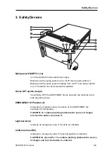
Страница 9: ... OFF the ARISTOMAT drives and sets the machine into a safe operating mode EMERGENCY OFF button 3 releases an emergency stop the drives of the ARISTOMAT are switched off immediately CAUTION To continue plotting eliminate the source of danger and turn the button to unlock it Light barrier 4 releases an emergency stop if it seizes an obstacle Collision shut off 5 releases an emergency stop if it push...

Страница 10: ...ISTOMAT SL without Conveyor 1 Total work area on the table top 2 Traversing bridge 3 Slide 4 Tool carriage 5 Tool head 6 Passage between traversing bridge and table top Area between tool head and table top 7 Axis of material transport system 8 Bearing pocket ...

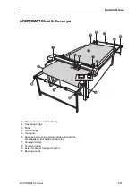
Страница 11: ... 1 Total work area on the table top 2 Traversing bridge 3 Slide 4 Tool carriage 5 Tool head 6 Passage between traversing bridge and table top Area between tool head and table top 7 Conveyor clamp 8 Conveyor return 9 Axis of material transport system 10 Bearing pocket ...

Страница 12: ...1 12 ARISTOMAT SL Series Caution Areas ...

Страница 13: ...ber 2000 Gesetz über die elektromagnetische Verträglichkeit von Geräten EMVG 89 336 EWG in der Fassung vom 30 08 1993 EN 292 Teil 1 u 2 1991 11 Sicherheit von Maschinen EN 294 1992 08 Sicherheitsabstände gegen das Erreichen von Gefahrenstellen mit den oberen Gliedmaßen EN 50 082 1997 11 Störfestigkeit DIN VDE 0113 Teil 1 02 86 EN 60204 Teil 1 1998 11 Unfallverhütungsvorschrift Grundsätze der Präve...

Страница 14: ......

Страница 15: ...Teil 1 u 2 1991 11 Sicherheit von Maschinen EN 294 1992 08 Sicherheitsabstände gegen das Erreichen von Gefahrenstellen mit den oberen Gliedmaßen EN 1012 Teil 1 und 2 Sicherheitsanforderungen Kompressoren und Vakuumpumpen EN 50 082 1997 11 Störfestigkeit EN 61000 6 Teil 1bis 4 Elektromagnetische Verträglichkeit EMV Fachgrundnormen Störaussendungen DIN VDE 0113 Teil 1 02 86 EN 60204 Teil 1 1998 11 D...

Страница 16: ......

Страница 17: ...Basic Elements of the ARISTOMAT SL 131O 1317 1617 1625 User s Manual Chapter 2 ...

Страница 18: ... 2004 by ARISTO Graphic Systeme GmbH Co KG Issue Januar 2004 Article No 00001 8898 E ...

Страница 19: ...ds 10 Placing and fixating material 10 3 System Start Up 11 Elements of operation 11 Main power ON OFF 12 EMERGENCY OFF button 12 Drives OFF switch red 12 Drives ON switch green 12 Monitor option 12 Joystick 12 Release joystick 12 Food switch vacuum pump 12 Air maintenance unit 12 Control panel 13 Display 13 Function keys 13 Direction keys 14 Command keys 14 Switching on the ARISTOMAT 16 4 Menu Ov...

Страница 20: ...ts 23 Menu Level 1 24 PARAMETER 24 ANGLE 24 SMOOTHING 26 CIRC RESOL ARC RESOLUTION 26 SMOOTH LEVEL 26 SWITCHING ON SPEEDBOOSTER 27 SPLINE 27 ACCELERATION 28 SPEED 28 PROJECTION of Plots 28 MIRRORING 28 SCALE 29 ROTATION 29 Menu Level 2 30 SAVE 30 SAVE CUSTOMER CONFIGURATION 30 LOAD FACTORY SETTINGS 30 HOST 31 HOST TEST 31 LANGUAGE 31 EMULATION 31 PLOTTER TYPE 31 FORMAT 32 INTERFACE 32 BAUD RATE 32...

Страница 21: ... 5 Contents Menu Level 3 33 MATERIAL WIDTH 33 LOWER OPTION 33 ORIGIN SWING 33 ON OFF 33 WIDTH 33 STEP 33 ROT OPTION 34 6 Periodic maintenance 35 7 Data interface 37 Connector and pin assignment 37 8 Specifications 39 9 Technical Hints 40 ...

Страница 22: ...2 6 Basic Elements of the ARISTOMAT SL Contents ...

Страница 23: ...h high speed and reliability ARISTOMAT machines cut computer con trolled patterns and originals They are suited also for commercial sized pattern and particularly for stiff material Everywhere there are special requirements for flexibility and precision In the meantime ARISTO presents an abundant offer of cutters with var ious tool heads material transport systems and accessories In this chapter o...

Страница 24: ...re machine Overview ARISTOMAT SL without Conveyor 1 Table top 2 Tool carriage 3 Main power ON OFF 4 Operator console 5 Traversing bridge 6 Air maintenance unit option 7 Pressure reducer option 8 Connector coupler plug 9 Machine control 10 2 Main power ON OFF with Electrical Transition Point only maschines with a pump system starting from 3 kW 11 Foot switch vacuum pump 12 Valve slide for vacuum zo...

Страница 25: ...e 5 Traversing bridge 6 Conveyor clamps 7 Maintenance unit compressed air 8 Pressure reducer option 9 Connector coupler plug 10 Machine control 11 2th Main power ON OFF with Electrical Transition Point only maschines with a pump system starting from 3 kW 12 Foot switch vacuum pump 13 Valve slide for vacuum zones 14 Identification plate at the machine control ...

Страница 26: ...re size of 5µm as replacements in the air maintenance unit Connecting the power supply Up to 1 1 kW pump system the machine must be attached to 230 V 50 60 Hz with 16 A Starting from 3 kW pump system the machine must be attached to 400 V 50 Hz 3 phase fixed connection with 16 A with a 3 kW pump system and or 20 A with 5 5 kW pump system These works may be carried out by qualified personnel only In...

Страница 27: ...de 7 Main power ON OFF 2 Foot switch vacuum pump 2th main power ON OFF with 3 Maintenance unit compressed air Electrical Transition Point 4 EMERGENCY OFF button 8 Monitor option 5 Drives OFF switch 9 Joystick 6 Drives ON switch 10 Release Joystick 11 Control panel only machines with a pump system starting from 3 kW ...

Страница 28: ...s the ARISTOMAT drive system ON Monitor option available only in conjunction with the Remote Eye or Automatic Eye System options The application is described in the chapter Print n Cut Remote Eye or Print n Cut Automatic Eye Joystick by pressing and holding the black unlock button down while tilting the joystick the tool head can manually be moved in any direction also diagonal The speed increases...

Страница 29: ...prompts for entries also displays operator errors error messages Function keys 2 are used for menu control The displayed function is selected with the corresponding key Example SETTINGS F1 F3 PLOT BUFFER ORIGIN VACUUM SETTINGS F2 F4 Press the key F4 to display the submenu and to set parameters NOTE Brackets with a function message indicate that this function is locked and cannot be served A relati...

Страница 30: ...s and The number can then be updated by using direction keys and SPEED 1000 0 1 Command keys 4 Following meanings are assigned to the function keys ESC selected functions and inputs are cancelled The previous menu is displayed ENTER confirms inputs The previous menu is displayed MENU changes between the individual menu levels START switches from menu setting to plot mode and respectively stop STOP...

Страница 31: ... deletes the origin already set and takes over the machine origin With SCAN TOOL F4 the inserted tool is automatically rec ognized blade pen VIEW Interrupts the active plot The tool moves to the far left corner of the table x max and y max giving an unobstructed view of the working surface Pressing the VIEW key again moves the tool to the previous position The job can be continued CAUTION In VIEW ...

Страница 32: ...SSURE Check the air supply and correct the air pressure settings The display prompts the operator unlock the Emergency off button then prompts switch on drives press green key Display F1 F3 REFERENCE MOVE F2 F4 CAUTION Maintain a safety distance during reference movements The traversing bridge and the tool carriage are moving automati cally press F3 to start the reference move Display EXECUTING RE...

Страница 33: ...d in four menu levels By repeated pressing of the key MENU successively the four levels in the display are represented and by pressures of the appropriate function keys F1 F4 one arrives into the appropriate submenus The tables attached under point Menu Tables show all functions with a reference in which manual a detailed description is to be found ...

Страница 34: ...2 18 Basic Elements of the ARISTOMAT SL Menu Overview Main Menu ...

Страница 35: ...Basic Elements of the ARISTOMAT SL 2 19 Menu Overview Menu Level 1 ...

Страница 36: ...2 20 Basic Elements of the ARISTOMAT SL Menu Overview Menu Level 2 ...

Страница 37: ...Basic Elements of the ARISTOMAT SL 2 21 Menu Overview Menu Level 3 ...

Страница 38: ...o blink to start the plot press START STOP If the data file send from the computer is larger than the buffer size indicated by minus BYTES on the display the function REPEAT cannot be used Pressing F1 prompts an error message REPEAT NOT POSSIBLE ESC TO LEAVE MENU When the plot buffer is empty display shows 0 BYTES pressing F1 prompts the message PLOT BUFFER EMPTY ESC TO LEAVE MENU LOAD TEST There ...

Страница 39: ...to set the laser pointer position as new origin MOVE TO ORIGIN press F3 to select the submenu ORIGIN press F4 MOVE TO ORIG The tool head moves to the actual origin Origin display press F3 to select the submenu ORIGIN toggle with ENTER to display polar or cartesian coordinates Select the POSITION POINTER press F3 to select the submenu ORIGIN press MENU and then F3 to select the submenu POSITION POI...

Страница 40: ...e the previous value is maintained PARAMETER The PARAMETER submenus offer settings which may influence plot quality and plot time press F1 PARAMETER for parameter settings with the function keys F1 F4 get to the following submenus ANGLE The angle setting effects the directional blade control and is of great im portance to obtain perfect cutting results The set angle defines an angle break between ...

Страница 41: ...front of a turn The upper angle can be set from 10 to 90 degrees factory setting 20 cut rotate cut cut STOP lift rotate lower cut The setting LOWER ANGLE defines the minimum angle to halt and up date the tool without lifting prior to cutting in the new direction The lower angle can be set from 0º to 45º factory setting 10º cut rotate cut cut STOP rotate cut ...

Страница 42: ... Adjustable only via HPGL instructions AA AR CI SMOOTH LEVEL The smooth levels serve to enhance quality and speed when processing plot data There are HPGL plotter drivers that supply plot data adequate to use with common pen plotters but produce unsatisfactory results on precision cutting plotters When the vector length in a plot file matches or is close to the plotter resolution the tool changes ...

Страница 43: ...ER A dynamic vector preview and a different velocity profile is activated The Speedbooster generates flowing motion NOTE The use of smooth levels or Speedbooster may result in some loss of contour accuracy SPLINE A function to smooth curves Vector strings are converted to smooth curves ON OFF turns the spline function ON or OFF With ADJUSTMENT SPLINE ANGLE defines the angle break between vectors t...

Страница 44: ...m 1 through 1200 factory setting 1000 100 Non productive motion pen up is always executed at maximum velocity PROJECTION of Plots Mirroring rotation and scale are variables that can be applied with a plot press F1 PROJEKTION with function keys F1 F4 call the following submenus MIRRORING Mirroring flips an image to the front of the plotter over the Y axis All positive X motion becomes negative An o...

Страница 45: ...000 100 is scale 1 ROTATION Rotation is in increments of 90º ccw pivoting over the actual origin Select the angle of rotation by toggling with keys F3 and F4 An origin must be set and verified to warrant the plot fits on the table and the mate rial The origin must be at least a job height inside the work area when using 90º rotation ...

Страница 46: ... configuration When saved as customer configuration the settings apply as defaults after start up LOAD FACTORY SETTINGS Press F4 to reset the ARISTOMAT to factory default settings Note The machine will display the dialog in German Contact force 10 Acceleration 100 Baud rate 9600 7 8 BIT 8 BIT BYTE C Offset 0 MultiHead OT T M P Rot option Standard rotation Format DIN A3 Upper acceleration 100 Upper...

Страница 47: ...th the computer parameters Otherwise in online mode an error message is displayed during data transmission FRAME ERROR REC DATA PRESS ESCAPE KEY HOST TEST NOTE Before testing the delivered test plug must be connected to the 25 pins socket at the machine control system Press F1 to start the test of the serial interface In case of interface faults detailed error messages will be displayed see corres...

Страница 48: ...ge and AF advance full page With F3 or F4 the following paper formats sizes can be set HP 7475 A A B DIN A4 and DIN A3 HP 7580 A B C D E DIN A4 A3 A2 A1 A0 ARISTO A B C D E DIN A4 A3 A2 A1 A0 INTERFACE BAUD RATE Parameter for data transmission choose with F3 or F4 between 19200 9600 4800 2400 1200 600 and 300 Baud 7 8 BIT choose with F3 or F4 between 7 BITS BYTE 8 BITS BYTE PARITY choose with F3 o...

Страница 49: ...epeats with the tool in the raised position until halted with the STOP key Select PERFORM LOWER and START the plot cut continues performing tool down commands ORIGIN SWING This function enables to avoid the excessive use and wear of the convey or caused by repetitive production in the same conveyor location It al lows to automatically shift the origin hence the plot in selectable incre ments this ...

Страница 50: ...e to or destruction of the blade when running over obstacles on the table When it is assured that during the cut process there are no obstacles on the table the setting OPTIMIZE ROTATION can be selected When moving with the blade up between shapes this function turns the blade to the next cut direction during the approach to the next shape enhancing the system throughput The setting can be saved a...

Страница 51: ...essive cleaner or solvent do not let coolant or lubricant to guides and toothed racks in the air maintenance unit use 5 micron filters only observe statute and rules for waste disposal for the conveyor the cleaning interval depends on the processed materials When working with fabrics daily vacuuming may be neces sary Cleaning interval for single shift workload Daily ARISTOMAT machine outside clean...

Страница 52: ...Machine control inside take off dust with a vacuum cleaner Toothed rack underside the guide rail take off materi al dirt with a soft plastic brush Twice a year Dust collector placed at the bridge replace by new one Yearly Clean filter in piping system of the vacuum pump ...

Страница 53: ...gnment PIN I O Name Level 2 O Transmit Data TD 0 12 V 1 12 V 3 I Receive Data RD like Pin 2 4 O Request To Send RTS constant 12 V On 7 Signal Ground GND 20 O Data Terminal Ready DTR On 12 V I O Input Output The connection between ARISTOMAT and IBM compatible computer with standard COM interface ARISTOMAT PC COM port PC COM port cable connector cable connector cable connector 25 pin male 9 pin fema...

Страница 54: ...ace The ARISTOMAT connects to the Modem port on an Apple Mcintosh con necting cable is optional Pin assignment Mac D Sub 25 D Sub 25 ARISTOMAT 8 pin round male female 25 pin male 1 6 6 4 2 5 5 20 3 2 2 3 4 7 7 7 5 3 3 2 6 not used 7 not used 8 not used ...

Страница 55: ...Acceleration Max 1 1 G adjustable via menu or software Drive system Digital servo drives Serial interface RS 232C V 24 D Sub connector 25 pins socket Data transmission rate 300 baud up to 19200 baud Protocol XON XOFF or DTR Input buffer 400 KB Data format HPGL compatible with extended instruction set Operating Integrated control panel with function keys and double spaced display Multilingual Engli...

Страница 56: ...er contain a HPGL instruc tion that is not supported by the ARISTOMAT i e Line Type 1 The ARISTOMAT was not turned off during tool change 1 The main power switch was turned off before turning off the drives 2 The bridge or the tool carriage were moved to the limit switch 1 EMERGENCY OFF button is locked 2 Defective machine controller Remedy 1 These messages are for information only Only the last u...

Страница 57: ...ler 1 The motor temperature is too high 2 The air pressure is too low 1 The amplifier is overloaded or defective 1 Locking of the axis due to obstruction i e material 2 Material advance speed and or acceleration is too high 3 Defective machine control ler or motor encoder unit Remedy 1 Call a service technician 1 Switch drives off and check the tool for reasons to lock Press ESC and switch the dri...

Страница 58: ...NSMIT RECEIVE INTERFACE ERROR RTS DSR INTERFACE ERROR DTR CTS Cause 1 Defective machine controller 1 Interface parameters of ARISTOMAT and computer are not the same 2 Wrong or defective inter face cable Note After pressing ESC the MAIN MENU appears Press START STOP to continue the plot The machine continues to plot but the job will be incomplete 3 Defective host interface Remedy 1 Call a service t...

Страница 59: ...Material transport systems for ARISTOMAT SL User s Manual Chapter 3 ...

Страница 60: ... 2004 by ARISTO Graphic Systeme GmbH Co KG Issue Januar 2004 Article No 00001 8897 E ...

Страница 61: ...m its bearings 17 Loading material roll 18 Reversing the wind direction 21 Wind take up systems 22 Motorized wind device MAuf R 13xx MAuf R 16xx 22 Lifting the shaft from its bearings 23 Insert the core of a roll 24 Material take up device MAuf 13xx MAuf 16xx 25 2 Vacuum systems 26 Strip vacuum zones 27 ARISTOMAT SL 131O 28 ARISTOMAT SL 1317 29 ARISTOMAT SL 1617 30 ARISTOMAT SL 1625 31 Formatted v...

Страница 62: ...ttings 47 Switching on the VACUUM 47 BLOW ON 47 VACUUM 47 FEED 47 PARAMETER 47 DYNAMIC 47 LENGTH 48 VACUUM DELAY 48 MORE 48 START FEED 48 PICK UP 49 SUCTIONON 49 PICK UP 49 BOARD LIFTER 49 TABLE 49 PUT ON 49 STACK 49 6 Malfunctions 50 Unwinding device 50 Boardlifter 51 ...

Страница 63: ...rious selectable vacuum zone layouts Selective zone activation provides optimal vacuum hold down for any application Suction cups secure the material against slip during material advance Conveyor An air permeable conveyor belt runs over the entire work area of the ARISTOMAT and at the same time serves as underlay while cutting Conveyor clamps at each end of the bridge move the conveyor belt during...

Страница 64: ...ing up material Please read first the Safety Instructions in chapter 1 General The safety regulations listed there are completed by special safety and danger notes in this chapter Preparation of the material roll Note The roll core must be flush with the film at both ends figure 1 When this is not given it is advisable to trim the core figure 2 figure 1 figure 2 ...

Страница 65: ...rview This roll holder does NOT feature automatic film winding Properties of suitable rolls core diameter 30 mm 1 2 in outer roll diameter max 200 mm 7 9 in max roll width with ARISTOMAT 13xx is 1400 mm 55 in ARISTOMAT 16xx is 1700 mm 67 in max roll weight 20 kg 44 lbs 1 roll holder 2 unwind wind shaft ...

Страница 66: ... unwind wind shaft through the material roll place the unwind wind shaft with roll in the roll holder brackets pick the film end up feed it under the bridge and pull forward towards the front of the cutter table machine origin press green Drives ON switch on the console to turn the drives on switching on the vacuum ...

Страница 67: ...es NOT feature automatic film winding Properties of suitable rolls core diameter from 65 90 mm 2 55 to 3 5 in outer roll diameter max 300 mm 11 3 4 in max roll width with ARISTOMAT 13xx is 1400 mm 55 in ARISTOMAT 16xx is 1700 mm 67 in max roll weight 70 kg 154 lbs 1 bearing bracket 2 support cone 3 unwind wind shaft ...

Страница 68: ...ives must be switched OFF place the material roll onto the unwind wind shafts pick the film end up feed it under the bridge and pull forward towards the front of the cutter table machine origin press green Drives ON switch on the console to turn the drives on switching on the vacuum ...

Страница 69: ... max roll width with ARISTOMAT 13xx is 1400 mm 55 in ARISTOMAT 16xx is 1700 mm 67 in max roll weight 20 kg 44 lbs 1 roll support cone adjustable 2 lock screw 3 roll drive chuck fixed 4 clamp screw 5 film loop sensors 6 electronic control 7 mode select switch switch settings AUTO roll wind unwind control is active OFF roll wind unwind control is disabled MAN rewind material manually by holding the ...

Страница 70: ...trol must be set to OFF slide the roll onto the drive chuck so that the film unwinds towards the cutter table turning the lock screw 1 cw expands the chuck to fix the roll loosen the clamp screw 2 on the adjustable roll support cone slide the support cone towards the roll until the cone sits snug in the roll core tighten both screws 2 and 1 in this sequence ...

Страница 71: ...p sensor detects the film Note with every manual or automatic material advance the film un winds automatically until the loop sensor detects the film pick the material end up feed it under the bridge and pull forward towards the front of the table machine origin press green Drives ON switch on the console to turn the drives on switching on the vacuum ...

Страница 72: ...55 in ARISTOMAT 16xx is 1700 mm 67 in ARISTOMAT 13xx Conveyor is 1250 mm 49 in ARISTOMAT 16xx Conveyor is 1550 mm 61 in max roll weight 70 kg 154 lbs 1 electronic control 2 bearing bracket with drive slot 3 bearing bracket 4 support cone 5 unwind wind shaft 6 support cone 7 bearing brackets 8 reflector for light barrier 9 mode select switch switch settings a winding up automatic b OFF switched off...

Страница 73: ... with ARISTOMAT 13xx is 1400 mm 55 in ARISTOMAT 16xx is 1700 mm 67 in ARISTOMAT 13xx Conveyor is 1250 mm 49 in ARISTOMAT 16xx Conveyor is 1550 mm 61 in max roll weight is 70 kg 154 lbs 1 electronic control 2 bearing bracket with drive slot 3 support cone 4 unwind wind shaft 5 support cone 6 bearing bracket 7 reflector for light barrier 8 mode select switch switch settings a winding up automatic b ...

Страница 74: ...AT 13xx Conveyor is 1250 mm 49 in ARISTOMAT 16xx Conveyor is 1550 mm 61 in max roll weight is 120 kg 264 lbs 1 electronic control 2 bearing bracket with drive slot 3 support cone 4 unwind wind shaft 5 support cone 6 bearing bracket 7 reflector for light barrier 8 EMERGENCY OFF button 9 mode select switch switch settings a winding up automatic b OFF switched off c unwind manually by holding the swi...

Страница 75: ...he vacuum holes of the zone 1 see illustration When changing the material roll only the right support cone storage side must be adjusted to the new material roll width Lifting the shaft from its bearings CAUTION The drives must be switched OFF depress the mode select switch manual figure 1 until the drive slot reaches its vertical position figure 2 figure 1 figure 2 lift the unwind wind shaft vert...

Страница 76: ... pull it from the shaft Loading material roll Light to medium weight rolls feed the wind unwind shaft through the material roll Load the roll so that the material unwinds towards the cutter table Note The material unwind device MAbHD features an additional switch to control the wind direction see Reversing the wind direction ...

Страница 77: ... rolls it is advisable to use a lift or hoist Use caution when placing the roll in the brackets danger of bruising place the material roll in a sling or belts and feed the roll feed shaft through the roll core slide the right support cone back onto the shaft locate tightly in the roll core and tighten the screw ...

Страница 78: ...CAUTION danger of bruising lower the heavy material roll carefully with the hoist into the two bearing brackets CAUTION When lowering the roll too fast dropping it the bear ings or brackets may damage Note The actuation ring for the safety switch must be seated correctly in its groove unroll the material into a loop and lay it onto the cutter table top set the mode select switch on the electronic ...

Страница 79: ... figure 1 figure 2 Figure 1 shows the material loop when the process coat faces roll out side Setting the direction control switch to the according pictogram left activates the feed in that direction Figure 2 shows the material loop when the process coat faces roll in side Setting the direction control switch to the according pictogram right activates the feed in that direction ...

Страница 80: ...mm 55 in ARISTOMAT 16xx is 1700 mm 67 in ARISTOMAT 13xx Conveyor is 1250 mm 49 in ARISTOMAT 16xx Conveyor is 1550 mm 61 in max roll weight is 70 kg 154 lbs 1 electronic control 2 right side bearing bracket with drive slot 3 right support cone 4 unwind wind shaft 5 left support cone 6 left side bearing bracket 7 reflector for light barrier 8 mode select switch switch settings a winding up automatic...

Страница 81: ...g the shaft from its bearings CAUTION The drives must be switched OFF depress the mode select switch manual until the drive slot reaches its vertical position lift the unwind wind shaft vertically up loosen the left support cone using a 4mm hex key and pull it from the shaft ...

Страница 82: ...e left support cone back onto the shaft locate tightly in the roll core and tighten the screw locate the shaft first in the left side bearing bracket and than on the right side insert the drive flat vertical in the drive slot The actuation ring for the safety switch must be seated correctly in its groove see figure lead the material in a loop on the core ...

Страница 83: ...ctronic control to AUTO press green Drives ON switch The material windsup automatically until the light barrier detects the loop Material take up device MAuf 13xx MAuf 16xx This material take up device catches and winds the film core less as the material advance feeds it off the cutter table top ...

Страница 84: ...able with a wide raster 40 mm x 40 mm for non air permeable materials such as film or with a denser raster 27 mm x 27 mm for air permeable materials also for materials that require high processing forces and or for small parts production Conveyor machine systems feature the dense hole pattern 27 mm x 27 mm as a rule Matrix zones tiles with dense hole pattern 27 mm x 27 mm for single sheet processi...

Страница 85: ...e vacuum zones are opened or closed using 1 or 2 vacuum slide valves By using 2 valve slides front and rear it needs to be observed that both slides are set the same to avoid uneven vacuum hold That does not apply to ARISTOMAT SL 1625 The valve slide carries a lock in groove for each zone and features mark ing rings to serve orientation figure 1 close zones lift the slide out of its groove push in...

Страница 86: ...3 28 Material transport systems Vacuum systems ARISTOMAT SL 131O ...

Страница 87: ...Material transport systems 3 29 Vacuum systems ARISTOMAT SL 1317 ...

Страница 88: ...3 30 Material transport systems Vacuum systems ARISTOMAT SL 1617 ...

Страница 89: ...erial transport systems 3 31 Vacuum systems ARISTOMAT SL 1625 The ARISTOMAT SL 1625 has 2 x 6 vacuum zones Zones 1 through 6 can be opened independent from zones 7 through 12 Zones 1 and 7 are always open ...

Страница 90: ...se vacuum plates are available for the ARISTOMATs 131O and 1317 without conveyor only The vacuum zones are opened or closed using a vacuum slide valve Zone 1 is always open the zones 2 through 5 are consecutively opened One cannot open i e zone 4 and 5 only ARISTOMAT SL 131O ...

Страница 91: ...Material transport systems 3 33 Vacuum systems ARISTOMAT SL 1317 ...

Страница 92: ...o the machine model transversely sub divided into 4 to 9 additional sections The zones are approx 270 mm 10 6 in wide and each section has its assigned slide valve They can independently be opened or closed CAUTION Operate the matrix vacuum slide valves only with the drives switched off danger of bruising from the bridge With conveyor machines all matrix zones must be open during manual or automat...

Страница 93: ... machines with two slides front and rear both slides must be open alike open matrix zones the figure below shows 3 using slides 2 The vacuum is only active in the area represented here graily now The following layouts show the division and numbers of matrix zones for each machine model ...

Страница 94: ...3 36 Material transport systems Vacuum systems ARISTOMAT SL 131O 5 strip zones and 4 matrix zones ...

Страница 95: ...Material transport systems 3 37 Vacuum systems ARISTOMAT SL 1317 5 strip zones and 7 matrix zones ...

Страница 96: ...3 38 Material transport systems Vacuum systems ARISTOMAT SL 1617 6 strip zones and 7 matrix zones ...

Страница 97: ...Material transport systems 3 39 Vacuum systems ARISTOMAT SL 1625 2 x 6 strip zones and 9 matrix zones ...

Страница 98: ...le in their relative distance to each other and their clearance above the material The number of suction cups depends on the machine model With narrow material some of the suction cups can be disabled by closing a valve A precise material advance is accomplished by positioning the suction cups evenly spaced across the material width and their clearance above the material adjusted correctly to the ...

Страница 99: ...4 lower the extrusion bar with suction cups by depressing F2 VACUUM F3 FEED F4 PICK UP F4 LAY DOWN in sequence Note The suction cups start picking up the material after they lowered and the table vacuum switches to the BLOW mode 5 Loosen the wing screws at the suction cup holders and position the suction cups equidistant over the material width Switch off one or both outside suction cups for narro...

Страница 100: ...r is only applicable with materials which could not or shall not suck in For the material advance of this materials there is a clamping bar mounted to the bridge During the advance cycle the bar lowers and squeezes the material lightly against the conveyor belt Combined with the conveyor the material advances securely ...

Страница 101: ...heet width and length depend on the machine model ARISTOMAT SL 13xx W x L max 1200 mm x 1200 mm 47 1 4 in x 47 1 4 in ARISTOMAT SL 16xx Wx L max 1500 mm x 1200 mm 59 in x 47 1 4 in The sheet material must lay on a palette standard Europalette Stack height including the palette min 120 mm 4 3 4 in max 700 mm 27 1 2 in 1 board lifter arm 2 suction panel 3 vacuum zone markings 4 stripper 5 vacuum sli...

Страница 102: ...es 5 and 6 only Note With narrow materials please close the unused zones in order to avoid an attenuation of the vacuum CAUTION The drives must be turned off Set the material palette about 100 mm 4 inch away from the machine The board lifter arm must lower onto the first third board area closest to the machine so that the sensor can touch the material plate surely Use the vacuum slide to open the ...

Страница 103: ...ack of sheets 1 and by suction picks a sheet up In the then following transport of the sheet the board lifter arm pauses does a few short jerks to throw off any unintended picked up sheet and then puts the sheet onto the table top 2 While the board lifter arm returns to the stack another material advance occurs transporting the sheet for processing towards the front of the table 3 Simultaneously t...

Страница 104: ...3 46 Material transport systems Menu Overview 4 Menu overview Only for the Boardlifter in MAIN MENU press MENU to call the following submenue ...

Страница 105: ...itched off during production mode FEED Note With conveyor machines having a matrix vacuum table top all vac uum zones must be open while advancing the material in manual or auto matic mode Various parameters i e speed acceleration and advance length can be set in the submenu under FEED In the main menu press F2 VACUUM and select FEED with F3 PARAMETER DYNAMIC SPEED advance speed can be set in incr...

Страница 106: ...om the cur rent position using the feed length entry via menu or a feed length from an HPGL instruction see PARAMETER LENGTH CORRECTION This compensation feature is used to make adjustments for the precise processing of fabrics because fabrics can stretch during advance Corrections are not necessary when working with rigid materials factory settings for correction values and 0 START FEED Note The ...

Страница 107: ...chines with clamping bar lower the bar and lock the material on the conveyor The material and or the conveyor with material can be moved forth and back using the directional keys BOARD LIFTER TABLE moves the board lifter arm over the table The display reads BOARD LIFTER ACTIVE PUT ON executes a sheet delivery cycle The board lifter arm lifts a sheet from the stack and places it on the table top A ...

Страница 108: ...nuously or not at all The light barrier does not respond Check whether the reflector is covered The unwind device does not respond Check the control electronics fuse underneath Unscrew the fuse holder and remove the fuse Replace a defective fuse and re install the fuse holder The unwind device does not respond The actuation ring is not seated cor rectly in its groove preventing it from activating ...

Страница 109: ...fter Does not lift a sheet error message ERROR BOARDLIFTER MOTOR PRESS ESC KEY TO CONTINUE vacuum zones are not open check whether vacuum zones are open sensor does not feel a material sheet the material stack is not properly set up the sheets lay skewed ...

Страница 110: ...3 52 Material transport systems Malfunctions ...

Страница 111: ...Chapter 12 ARISTOMAT SL Safety Devices User s Manual ...

Страница 112: ... 2005 by ARISTO Graphic Systeme GmbH Co KG Issue August 2005 Article number 0000 18857 E ...

Страница 113: ...y Devices for ARISTOMAT SL 12 3 Contents Contents 1 Introduction 4 2 Overview 5 3 During operation 6 4 Check Functions 7 Light barrier 7 Collision shut off 8 5 Adjustment of the light beam 9 6 Maintenance 11 ...

Страница 114: ...kness of the processed material change the light barrier must be re adjusted max range for adjustment 30 mm above the protective underlay In addition the light barriers are equipped with a Collision Shut off On contact with obstacles persons or objects an EMERGENCY STOP is activated and the drives are switched off immediately Note The faultless function of the Standard light barrier and the Collis...

Страница 115: ... Safety light barrier Category 2 EN 954 1 optional Standard light barrier 1 Light barrier transmitter 2 Light barrier receiver 3 Collision Shut off 4 Drives ON switch Safety light barrier 1 Light barrier receiver 2 Light barrier transmitter 3 Collision Shut off 4 Drives ON switch ...

Страница 116: ...ht barrier or the Collision Shut off a Standard light barrier The display shows the message SWITCH DRIVES ON PRESS GREEN KEY Switch ON the drives with the green key at the operator console The drives are switched on and the main menu is displayed b Safety light barrier Switch ON the drives with the green key at the operator console to confirm the message The display shows the message SWITCH DRIVES...

Страница 117: ...mm on top of the material Press the green DRIVES ON switch at the operator console to turn the drives ON switch ON vacuum Move the bridge with the direction keys at the operator console over the objects The 7 mm object must release an EMERGENCY STOP If no EMERGENCY STOP is released the light beam adjustment is incorrect Re adjust the transmitters and receivers CAUTION The light beam may not exceed...

Страница 118: ...lision Shut off is mechanically connected to the light barriers On contact with an obstacle the crash pad 1 slides in front of the light beam 2 The light beam is interrupted and activate an EMERGENCY STOP If no EMERGENCY STOP is activated please check if this mechanism is blocked ...

Страница 119: ...smitter beam must hit the receiver With optimum light reception signal indicator is ON see figure The light barriers must respond to objects of 7 mm height above the material in the working area of the traversing bridge and activate an EMERGENCY STOP Turn the screws on both transmitters and both receivers with same number of turns using a LN key 2 5 mm One turn 1 mm To increase the height turn cw ...

Страница 120: ...receiver and the transmitter are ON and the drives can be switched ON The light barrier is not adjusted correctly Standard light barrier The red LED on the receiver is OFF and the drives cannot be switched ON Safety light barrier The LEDs on the receiver and the transmitter lights red and the drives can not be switched ON Following fault message is displayed EMERGENCY STOP FAULT X AXIS AIR PRESSUR...

Страница 121: ...egory 2 EN 954 1 The safe function of the system is automatically checked after each power on In addition a cyclic testing is carried out during operation check height adjustment see 4 Check functions Collision Shut off Before every operation check functions see 4 Check functions In regular intervals clean the optical surface with mild detergent Do not use hard or sharp objects for cleaning Avoid ...

Страница 122: ...12 12 Safety Devices for ARISTOMAT SL Maintenance ...

Отзывы: