VPP2-06-xV/xx-CE1017_Instruction manual for the use of_Gebrauchsanweisung_Návod k použití__29426400_2en_de_cz_09/2021
Page 8
www.argo-hytos.com
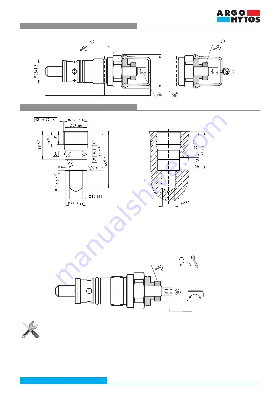
Dimensions mounting cavity QP2
Dimensions VPP2-06
in millimeters (in)
Before commissioning the hydraulic circuit, check that the valve is properly tightened in the cavity. If the valve was set by the manufacturer, only
check the integrity of the seal.
6.3 Commissioning
If the valve is set by the user after installation into the hydraulic circuit, the procedure is as follows:
Setting the valve cracking pressure
After removing the plastic cover using a size 17 wrench, loosen the M10x1 (position 5) locking nut by turning it counter clockwise.
Using a size 5 Allen key, turn the adjusting screw (position 4) to set the required valve cracking pressure at the given volume flow.
Turning the adjusting screw clockwise increases the cracking pressure value. Either a manometer or a pressure sensor must be
connected to the circuit (at least temporarily) to check the set pressure. Check the correct setting of the cracking pressure several
time. Reduce the system pressure below the set cracking pressure. Slowly increase the pressure value and read the value when the
valve opens and the system pressure drops. After setting the pressure, secure the position of the setting screw using a size 17 inbus
wrench and tightening the locking nut clockwise to 10 + 1Nm. Check the setting again to ensure that it has not changed while
tightening the nut. Feed the sealing wire through the hole in the adjusting screw and the plastic cover and fit the cover. Use sealing
pliers to secure the position of the seal. This protects the valve setting against unintentional change.
Type T
Type L
64,5 (2.54)
52 (2.05)
38 (1.50)
VPP2-06-SV/xx-
CE1017-xx-x
x
Ø
H
A
VPP2-06-SV/xx-
CE1017-xx-x
x
80+5 Nm
(59+3.7 lbf.ft)
32
+p
p
5
17
10+1 Nm
(7.4+0.7 lbf.ft)
AXIAL.
Adjuster
screw (4)
VPP2-06-xV/xx-CE1017-xx-xx
17
5
+p
p
Locking nut
10+1 Nm
(7.4+0.7 lbf.ft)


