background image

14

SNO-2218

2. Secure the tie rod assembly to the steering post using

a new M10 nut.

 Be sure to align the tie rod ball

joint alignment tab with the steering post.

 Tighten

to 35 ft-lb.

SNO-2219

3. Secure the right-side steering boot to the chassis

using the existing push rivets.

XM134A

4. Secure the top of the steering post to the steering

support using the existing retaining plate and nuts.

Tighten to 96 in.-lb.

SNO-357

5. Install the expansion chamber using the existing

springs; then connect the exhaust temperature sensor

to the main harness.

6. Position the hood onto the snowmobile and connect

the hood harness connector.

7. Secure the hood with the six torx-head screws and

tighten securely.

8. Install the access panels onto the lower console; then

close the access panels and secure with the clip.

Steering Post (XF HC/M)

REMOVING

To remove the access panel and hood, use the following

procedure:

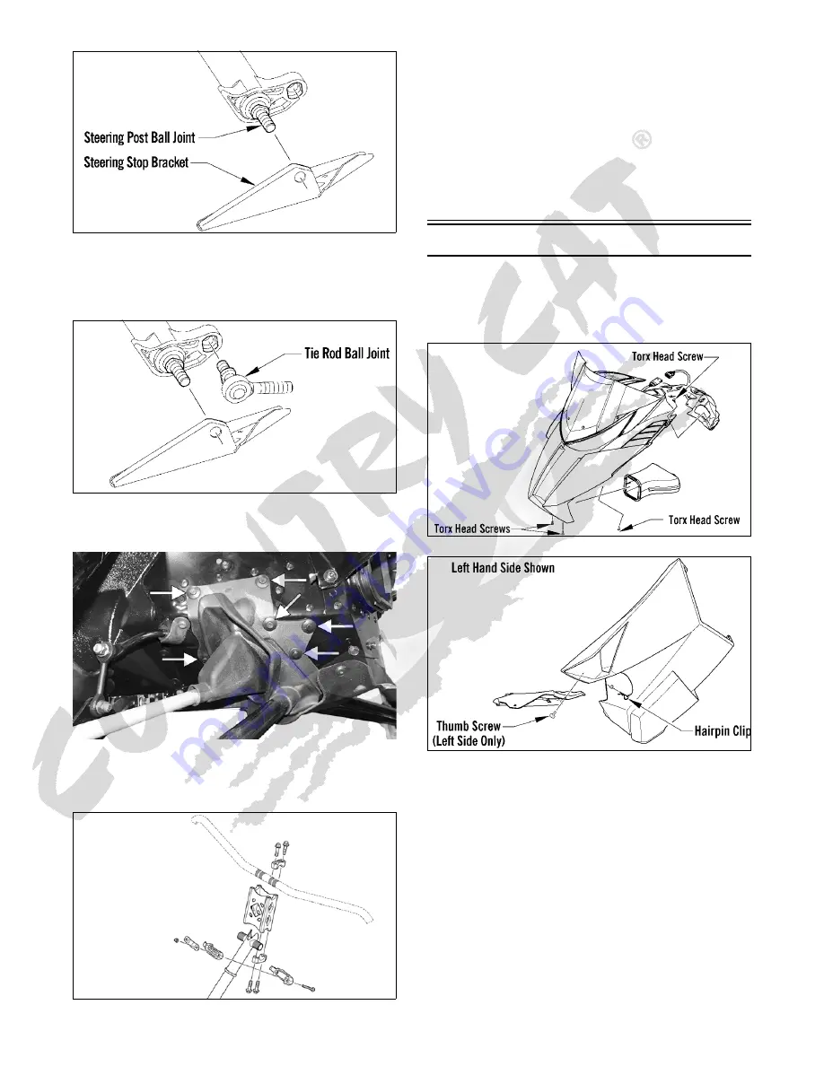
0746-793

0746-800

1. Remove the hairpin clip from the pin located at the

front of the access panel; then unscrew the thumb

screw. Move the panel up and off the pin; then swing

the panel all the way out and unhinge the panel from

the lower console.

2. Remove all six torx-head screws securing the hood.

3. Locate the hood harness connector (located under the

center vent between the intake vents) and unplug the

connector; then move the hood slightly forward and

remove the hood.

4. Disconnect the exhaust temperature sensor from the

main harness; then remove all springs securing the

expansion chamber. Remove the expansion chamber.

Содержание 2014 XF 2-STROKE

Страница 1: ...SNOWMOBILE SERVICE MANUAL 2014 ZR XF M 2 STROKE...

Страница 2: ...snowmobile decals display the words Warning Caution and Note to emphasize impor tant information The symbol WARNING identifies personal safety related information Be sure to follow the directive becau...

Страница 3: ......

Страница 4: ...System 91 Fuel Systems 92 EFI System 92 Individual Components 92 Self Diagnostic System Codes 6000 95 Self Diagnostic System Codes 8000 95 Fuel Pressure Regulator 96 Throttle Body Assembly 96 Throttle...

Страница 5: ...tion models During the break in period a maximum of 1 2 throttle is recommended however brief full throttle accelerations and variations in driving speeds contribute to good engine break in 6000 The A...

Страница 6: ...an the sea level calibrations work best The driven spring will also affect driven clutch tuning Tighten the spring and RPM will increase Loosen the spring and RPM will decrease The spring should be us...

Страница 7: ...the track to sag in the middle and rub on the top part of the rear suspension arm Track Carefully matching the riding requirements to the type of track will ensure the maximum use of all available en...

Страница 8: ...owmobile out of storage and correctly pre paring it for another season will assure many miles and hours of trouble free snowmobiling Arctic Cat recom mends the following procedure 1 Clean the snowmobi...

Страница 9: ...e Along with these major areas other areas should be checked and adjusted Below is a list of items to check after the break in period The recommended mileage for this inspection is between 100 and 300...

Страница 10: ...haft is still supported on the outer bearings using V blocks 728 144A NOTE Measure in from the shaft end the specified amount when checking runout at points D and F When checking runout in the center...

Страница 11: ...52 2 28 ohms orange orange Servomotor 12 DC Volts red black counterclockwise black red clockwise black red counterclockwise red black clockwise Voltage Regulator Rectifier 9 14 5 DC Volts red blue bl...

Страница 12: ...ch ZR 6000 El Tigre 6000 RR 0 5000 Green 64g Black Blue 42 40 0627 083 42 4600 81 8200 22T 48T 90 ZR 8000 LXR Sno Pro LTD RR 0 5000 Green 73 5g Black Blue 44 40 0627 083 36 4000 81 8200 21T 41T 86 M 6...

Страница 13: ...90 82 85 87 89 91 94 96 98 101 22 48 0 458 90 88 90 93 95 98 100 103 105 108 21 41 0 512 86 98 101 104 106 109 112 115 117 120 20 38 0 526 84 101 104 107 109 112 115 118 121 123 21 38 0 553 84 106 109...

Страница 14: ...8 70 5 90 7 72 ZR Sno Pro XF Sno Pro 12 80 18 40 5 60 7 72 ZR RR 12 80 18 60 5 76 2 50 M STD 11 81 17 90 6 09 1 29 M Sno Pro 12 00 17 55 5 55 7 36 HCR Turbo 12 30 17 80 6 59 7 36 ZR STD ZR 8000 LXR 12...

Страница 15: ...Support Spar 20 Steering Support Upper Console 30 in lb Steering Arm Chassis 8 A Arm Upper M Chassis 9 A Arm Upper Chassis 23 A Arm Lower Chassis Front 65 A Arm Lower Chassis Rear 45 A Arm Spindle 45...

Страница 16: ...nector then move the hood slightly forward and remove the hood 4 Disconnect the exhaust temperature sensor from the main harness then remove all springs securing the expansion chamber Remove the expan...

Страница 17: ...head screws and tighten securely 8 Install the access panels onto the lower console then close the access panels and secure with the clip Steering Post XF HC M REMOVING To remove the access panel and...

Страница 18: ...post to the chassis Account for both steering post blocks and retaining plate SNO 2226B 8 Carefully remove the secondary steering post from the snowmobile 9 Remove and discard the cotter pin C and ny...

Страница 19: ...cks or wear INSTALLING 1 Insert the telescoping steering post into the steering support along with two bushings then secure the steering post using the existing retaining ring SNO 740A NOTE Verify the...

Страница 20: ...the secondary steering post using the machine screw and nut Tighten to 20 ft lb 10 Install the expansion chamber using the existing springs then connect the exhaust temperature sensor to the main har...

Страница 21: ...NOTE Assure that the cotter pin slot in the cap screw is still horizontal with the ski see illustration then proceed to step 5 5 Install a new cotter pin from the back side of the ski cap screw and s...

Страница 22: ...w lock nuts Tighten to 45 ft lb NOTE The weight of the snowmobile will allow the ball joints to seat into the spindle before tightening the nuts 3 Place the tie rod with washer into position on the sp...

Страница 23: ...ing cap screw flat washers and nut Tighten to 96 in lb SNO 225A 2 Place the steering tie rod into position on the steering post Secure with a new nyloc nut Tighten to 35 ft lb SNO 351 NOTE Make sure t...

Страница 24: ...7 8 in behind the spindle Record the measurements taken for the left side 729 887A 0734 408 6 Place the straightedge against the outside edge of the track so it lies near the inside edge of the right...

Страница 25: ...ivets securing the steering boot to the chassis then slide the boot away from the snowmobile XM134A 3 Remove the torx head screws securing the front skid plate to the chassis then remove the front ski...

Страница 26: ...taking all pressure off the skis 2 Remove the cap screws securing the shock absorber to the chassis and spindle then remove the shock absorber Account for all mounting hardware NOTE Note the number of...

Страница 27: ...nt Bumper REMOVING INSTALLING 1 Remove all torx head screws securing the front bum per then remove the bumper 2 With the bumper in position install all torx head screws Tighten securely Seat Assembly...

Страница 28: ...he lower console Pull back and remove the seat cover and foam 0747 530 2 Position the seat foam into the seat cover by first aligning the front of the foam with the front of the seat base cover A then...

Страница 29: ...wflap to the rear bumper using new rivets 2 Secure the front of the bumper to the chassis using the existing machine screws and nuts Tighten securely 3 Install skid frame assembly using two existing m...

Страница 30: ...d from the housing Do not touch the glass portion of the bulb If the glass is touched it must be cleaned with a dry cloth before installing 1 Disconnect the headlight harness connector from the bulb t...

Страница 31: ...switch HIGH beam position DO NOT USE LOW BEAM 6 Observe the headlight beam aim Proper aim is when the most intense beam is centered on the vertical mark 5 cm 2 in below the horizontal mark on the aimi...

Страница 32: ...t temperature sensor from the expansion chamber 2 Remove all springs securing the expansion chamber and resonator then remove the expansion chamber and resonator 3 Remove the torx screw from the drive...

Страница 33: ...EL 006A 13 Loosen the four clamps securing the throttle body then lift up the throttle body and disconnect the cool ant hoses Set the throttle body up and out of the way 14 Remove the intake boot fro...

Страница 34: ...for installation on the new engine Installing NOTE If the engine was replaced make sure to install the existing engine support plate and the exhaust manifold on the new engine Tighten the exhaust man...

Страница 35: ...onnectors and apply Dielectric Grease to the seal then connect all harness connectors making sure all wiring and coolant hoses are routed properly as noted in removing Install the main harness wrap NO...

Страница 36: ...the heat shield onto the two front locating pins B then secure it to the chassis with the two screws A Tighten securely EL 001A 28 Install the resonator and secure with the springs then place the exp...

Страница 37: ...ing the engine to the proper operating tem perature shut the engine off then open the access panels and inspect for any signs of coolant gasoline or oil leakage 36 Allow the engine to cool then check...

Страница 38: ...35 Assembly Schematic 6000 600_14_1 Torque Specification Tolerances Torque ft lb Tolerance 0 15 20 16 39 15 40 10...

Страница 39: ...36 600_14_2...

Страница 40: ...xpansion chamber 2 Remove all springs securing the expansion chamber and resonator then remove the expansion chamber and resonator 3 Remove the cap screw from the driven clutch and slide the driven cl...

Страница 41: ...ooling System the Engine Related Items section 13 Loosen the clamp securing the gasline hose to the throttle body and remove the hose then close off the hose and secure the hose up and out of the way...

Страница 42: ...ap screws and carriage bolt nut securing the PTO side chassis sup port to the shock mount bracket and chassis Remove the chassis support and account for the carriage bolt 24 Remove the torx head screw...

Страница 43: ...cure the coolant temperature sensor connector with a cable tie 13 Install the cylinder head vent hose PC178B 14 Place the recoil starter into position and secure with the cap screws Tighten in a criss...

Страница 44: ...th the springs then place the expansion chamber and gaskets into posi tion and secure to the exhaust manifold and resonator with the springs NOTE When installing the manifold springs the long hook por...

Страница 45: ...ne or oil leakage 39 Allow the engine to cool then check the coolant level and add coolant as necessary Verify the tight ening torque of the drive clutch CAUTION If the engine had a major overhaul or...

Страница 46: ...43 Assembly Schematic 8000 800_12_1 Torque Specification Tolerances Torque ft lb Tolerance 0 15 20 16 39 15 40 10...

Страница 47: ...44 800_12_2...

Страница 48: ...ler or suitable substitute remove the flywheel from the crankshaft by tightening the puller bolt using an pneumatic gun Account for the key NOTE To ensure the cleanliness of the flywheel magnets place...

Страница 49: ...isconnect the coolant hose from the back of the cyl inder head 10 Remove the cap screws with O rings securing the cylinder head in the order shown then separate the head from the cylinders Account for...

Страница 50: ...CWI 014 15 Lift the pistons clear of the connecting rods and remove the small end connecting rod bearings then remove the piston rings Keep each piston with its rings keep each piston pin and bearing...

Страница 51: ...or to turning the engine upside down remove the two crankcase torx screws A from the water pump side of the engine then remove the two cap screws B from the magneto housing CWI 075A CWI 023A 21 Tip th...

Страница 52: ...he mechanical water pump seal from the crankcase FC036 28 Using a pair of snap ring pliers remove the snap ring securing the inner seal in the crankcase 29 Using the hooked end of the tool pull the in...

Страница 53: ...ankcase halves for scoring pitting scuffing or any imperfections in the casting 3 Inspect all threaded areas for damaged or stripped threads 4 Inspect the bearing areas for cracks or excessive bearing...

Страница 54: ...shaft making sure the retaining pin hole A in the outer race of the bearing is properly positioned and will align with the retaining pin B in the crankcase IO019B REED VALVE ASSEMBLY 1 Carefully pry t...

Страница 55: ...CYLINDER CLEARANCE 1 Measure the piston skirt diameter 10 mm from the bottom of the piston just below the slot Once the measurement is final lock the micrometer CWI 080 2 Position a bore gauge between...

Страница 56: ...tal indicator reading 0747 810 3 If runout exceeds 0 002 in at any of the checkpoints the crankshaft must be either straightened or replaced Assembling NOTE The use of new gaskets and seals is recom m...

Страница 57: ...ward CWI 030A 8 Install the crankshaft into the upper crankcase half Be sure the alignment hole in each bearing is posi tioned over its respective retaining pin in the crank case then seat the cranksh...

Страница 58: ...16A 16 Tip the crankcase assembly up on the water pump side then pour Arctic Cat C Tec2 engine oil into the center cavity of the crankshaft until the oil is level with the shoulder of the shaft A CWI...

Страница 59: ...th an oiled piston pin NOTE The indicator arrow is found on the piston dome 23 Install the new circlips so the open end is directed either up or down 24 Rotate each piston ring until the ring ends are...

Страница 60: ...to 13 ft lb then 28 ft lb using the pattern shown 0747 890 NOTE At this point install the spark plugs then install the knock sensor Tighten the sensor to 18 ft lb 30 Install the coolant inlet hose to...

Страница 61: ...ipe the crankshaft and flywheel tapers clean using a clean lint free towel 37 Place the recoil cup in position on the flywheel and visually center then secure the cup with three cap screws and tighten...

Страница 62: ...remove the three starter clutch cap screws and remove the clutch CM138 CM139 2 Install the Flywheel Puller Insert onto the end of the crankshaft IO013 3 Using Flywheel Puller or suitable substitute r...

Страница 63: ...to the engine then remove the plate CM145D NOTE For assembling purposes note the indenta tion A of the stator plate is aligned with the harness opening B in the crankcase CM145C NOTE The stator plate...

Страница 64: ...unt for gasket s and alignment pins XM018 12 Remove the PTO side piston pin circlip from the PTO side piston then remove the MAG side piston pin circlip from the MAG side piston XM020A 13 Using Piston...

Страница 65: ...k valve assembly to the crankcase then remove the two screws securing the oil injection pump to the crankcase Remove the pump retainer and O ring and account for the two gaskets from the lower union C...

Страница 66: ...on the ends of the crankshaft tap on each cap screw head until the case halves separate Remove the cap screws CM158 24 Lift the bottom half of the crankcase off the top half 25 Lift the crankshaft fre...

Страница 67: ...he cylinder head in a figure eight motion until a uniform bright metallic finish is attained CYLINDERS 1 Using a non metallic carbon removal tool remove carbon buildup from the exhaust ports 2 Wash th...

Страница 68: ...s of the crankcase halves for trueness by placing each crankcase half on the surface plate covered with 400 grit wet or dry sand paper Using light pressure move each half in a fig ure eight motion Ins...

Страница 69: ...nkcase IO019B REED VALVE ASSEMBLY 1 Inspect the reed valves stoppers and valve blocks for cracks or any deterioration XM227 2 Wash the reed valves stopper and cage assembly in parts cleaning solvent a...

Страница 70: ...l lock the micrometer 2 Position a bore gauge between the micrometer points and move it from top to bottom and side to side to find zero then adjust the gauge to zero CWI 090 CWI 089 3 Place the bore...

Страница 71: ...ition the indicator contact point against the crank shaft at location point C center Zero the indicator and rotate the crankshaft slowly Note the amount of crankshaft runout total indicator reading 5...

Страница 72: ...the spring side of each seal faces inward 8 Apply oil to the crankshaft bearings then install the crankshaft into the upper crankcase half Be sure the alignment hole in each bearing is positioned over...

Страница 73: ...of grease to the sealing surface of the oil injection pump water pump driveshaft then place the Oil Seal Protector Tool at the end of the shaft FS191 15 Rotate the oil injection pump water pump drive...

Страница 74: ...ten to 18 ft lb then secure the sensor wire to the sensor with a cable tie 21 Position the ceramic rubber seal into the back side of the water pump impeller with the ceramic face of the seal directed...

Страница 75: ...lb 0742 257 26 With the bypass valve of the thermostat directed to the 12 o clock position install the thermostat and housing then in a crisscross pattern tighten the cap screws to 96 in lb CM157A CM...

Страница 76: ...ath the piston skirt and square the piston in respect to the crankcase then using a ring compressor or fingers compress the rings and slide the cylinder over the piston Remove the piston holder and se...

Страница 77: ...stall the spark plugs then install the knock sensor with the new lock plate tighten the sensor to 17 ft lb and bend the lock plate tabs up NOTE At this point pressure test the engine see the Engine Re...

Страница 78: ...reads of the flywheel cap screw then finger tighten with a large flat washer DO NOT TIGHTEN AT THIS TIME FC080 46 Secure the starter clutch while using the spanner wrench and tighten the three cap scr...

Страница 79: ...n low 11 Stator faulty Fuel pump or injector coil 12 ECM faulty 1 Fill tank 2 Replace dropping resistor 3 Remove obstruction replace vent hose 4 Remove obstruction replace pick up valve s 5 Replace re...

Страница 80: ...s 9 Replace bleed adjust oil injection pump 10 Replace reed petals 11 Refill coolant repair Thermostat repair Water Pump Assembly 12 Replace fuel with higher octane 13 Replace ECM CCU Problem Engine...

Страница 81: ...n the clamps securing the coolant hoses to the water pump then remove the hoses XM114A 2 Remove the seven cap screws securing the water pump cover then remove the cover and account for the O ring seal...

Страница 82: ...he shaft back out of the impeller 6 Remove the oil injection pump retainer and shaft from the opposite side of the crankcase Account for the shim located between the retainer and shaft flange FS226 7...

Страница 83: ...the sealing surface of the oil injection pump driveshaft then install Oil Seal Protector Tool at the end of the shaft Twist the shaft while pushing it through the oil and water pump seals until the s...

Страница 84: ...threads of the cap screw and tighten to 48 in lb XM112 10 Apply sealant to the crankcase seam then install the alignment pins into the crankcase if removed XM112A 11 Position the O ring into the wate...

Страница 85: ...gasket behind the cap screw Remove the impeller from the shaft CWI 082 NOTE If the impeller will not slide off the shaft start the cap screw into the shaft and tap on the cap screw driving the shaft...

Страница 86: ...aft Twist the shaft while pushing it through the water pump seals until the shaft gear engages with the drive gear of the crank shaft then remove the tool CWI 101 7 Position the shim on the retainer e...

Страница 87: ...LLING COOLING SYSTEM 1 Elevate the front of the snowmobile 30 60 cm 12 14 in 2 Remove the coolant tank cap and check coolant level The coolant tank should be filled to the coolant level line 3 Install...

Страница 88: ...d use discretion and sound judg ment when servicing a particular cooling system 0747 869 Recoil Starter 741 373B REMOVING 1 Tie a slip knot in the starter rope below the console and allow the rope to...

Страница 89: ...e end then wrap the rope counterclockwise around the roller leaving approximately 20 in of rope free of the roller 4 Apply low temperature grease to the main spring and hub 5 Align the hook in the end...

Страница 90: ...nsists of two circuits One circuit is a DC circuit operating the DC motor within the servomo tor and the other is a potentiometer measuring the pulley position based on voltage The computer within the...

Страница 91: ...ull the cable as far out as it will go then release Repeat three to four times The cable exhaust valve should move freely without binding If the cable exhaust valve does not move freely the exhaust va...

Страница 92: ...topper then slowly release the cable and remove it from the valve stopper FC113 Cleaning and Inspecting 1 Remove all carbon deposits with solvent and a soft abrasive such as a Scotch Brite pad 2 Inspe...

Страница 93: ...4 Slide the exhaust valve assembly into the cylinder XM017 5 Place the valve cover into position on the engine Secure with two cap screws Tighten to 96 in lb XM024A 6 Perform steps 5 8 in Cable Adjus...

Страница 94: ...ns The ECM receives input on engine RPM demand and exhaust temperature engine condi tion and adjusts the ignition timing accordingly This system is not adjustable and is maintenance free If a system f...

Страница 95: ...l rail The fuel pressure is maintained in the fuel rail by the fuel regulator With the fuel pressure maintained at a constant psi the ECM evaluates the information it receives from the electrical sens...

Страница 96: ...while overheating At this time the check engine light will be constantly on THROTTLE POSITION SENSOR This sensor is a potentiometer essentially a resistor This sensor transforms the throttle valve pos...

Страница 97: ...r PTO side must be entered using the CATT II Tool SNO 1235A 1 Lightly oil the injector seals using the C TEC2 engine oil then carefully install the injector into the fuel rail 2 Connect the wiring har...

Страница 98: ...a code is dis played on the readout screen the ECM is receiving input that is outside of its established parameters FZ001D Code Trouble P0112 Intake air temp sensor 1 circuit low P0113 Intake air tem...

Страница 99: ...ctor and from the throttle position sensor 2 Remove the coolant hoses from the throttle body assembly and plug them to prevent leakage 3 Remove the fuel supply hose from the fuel rail 4 Loosen the fla...

Страница 100: ...e throttle cable to the handlebar and steer ing post with cable ties 6 Adjust the throttle cable tension by turning the jam nuts in the appropriate direction until 0 030 0 060 in free play exists in t...

Страница 101: ...211B 3 Remove and retain the six torx head screws securing the fuel pump in the fuel tank then remove the retaining ring 4 Carefully remove the fuel pump and fuel pickup assembly from the gas tank not...

Страница 102: ...line hose to the fuel pump making sure it locks into place 7 Install the upper and lower consoles using existing machine screws then install the seat see the Steer ing and Body section hood and access...

Страница 103: ...ligned with the oil injection pump drive gear 4 Secure the pump with two screws coated with blue Loctite 243 Tighten screws to 96 in lb 5 Connect the oil delivery hoses to the adapter plates Secure wi...

Страница 104: ...attach the oil supply hose to the oil reservoir NOTE After testing the oil pump the oil pump must be correctly synchronized with the carburetors throt tle bodies see SYNCHRONIZING in this sub section...

Страница 105: ...ecure the right side skid plate using the existing screw 4 Bleed the oil injection system using the CATT II tool Instructions included with the tool NOTE If a new oil pump is being installed be sure t...

Страница 106: ...Install the rear spar tubes and secure to the chassis and steering support using the four cap screws Tighten to 23 ft lb XM210A XM212A 3 Connect the reverse alarm then use the two machine screws to s...

Страница 107: ...s shown below 2 With the throttle lever in the idle position the meter must read less than 1 ohm If the meter reads OL infinite resistance replace the control assembly 3 Move the throttle lever to the...

Страница 108: ...7 If the TPS is within the prescribed specification dis connect the adjustment tool harness from the TPS Connect the snowmobile TPS harness to the TPS NOTE Before installing the TPS harness connector...

Страница 109: ...ing the TPS to the throttle body and remove the sensor Installing 1 Install the new TPS onto the throttle shaft by align ing the flats on the throttle shaft cam with the flats on the sensor then rotat...

Страница 110: ...ust read less than 1 ohm between the ignition switch terminals 4 Rotate the key to the RUN position The meter must read OL infinite resistance Fuel Injector 1 Disconnect the fuel injector wiring harne...

Страница 111: ...gine and allow it to idle Meter reading must be within 11 14 AC Testing Oil Level Sensor The oil level sensor is a magnetic switch Its operation is based on a magnet located in the float The switch lo...

Страница 112: ...en 2 and 4 amps of solenoid coil current flow with the battery connected Method 2 1 Using the multimeter set to the DC Voltage posi tion check the relay as follows 2 Connect the red tester lead to the...

Страница 113: ...er Motor REMOVING 8000 1 Remove the seat and disconnect the battery then remove the hood and both access panels 2 Remove all springs securing the expansion chamber and resonator then remove the expans...

Страница 114: ...xpansion chamber and resonator 3 Remove the two screws A securing the heat shield to the chassis then remove the heat shield from the two front locating pins B and remove the heat shield EL 001A 4 Dis...

Страница 115: ...nion shaft slide the pinion gear spring retainer pinion spring and snap ring retainer note end for end orientation onto the shaft in their origi nal positions 2 Place new snap ring over the end of the...

Страница 116: ...he belt and driven clutch 6 Install the throttle body boot then install the throttle bodies making sure to connect the PTO side coolant hose oil pump rod and injection connections 7 Secure the throttl...

Страница 117: ...d secure using existing springs 9 Install the hood left and right side access panels 10 Connect both battery cables to the battery making sure both are secure then install the seat Troubleshooting Ele...

Страница 118: ...proper operation Headlight Dimmer Switch REMOVING TESTING 1 Remove the four screws securing the left side han dlebar control assembly then remove the control assembly from the handlebar 2 Disconnect t...

Страница 119: ...ing the left side han dlebar control assembly then remove the control assembly from the handlebar 2 Disconnect the handlebar thumb warmer harness from the switch 3 With the thumb warmer toggle in the...

Страница 120: ...red black servo terminal with the battery positive lead then contact the black red servo termi nal with the battery negative lead 3 The servo should rotate when the negative lead con tacts the black r...

Страница 121: ...rvomotor NOTE If the servo operates correctly and the poten tiometer test is correct but fails to operate when con nected to the ECM regulator rectifier at the designated RPM see Troubleshooting Servo...

Страница 122: ...119 Troubleshooting Servomotor SERVO1A14...

Страница 123: ...120 SERVO2rv14...

Страница 124: ...5490 34 C 29 F 4 574 302000 36 C 97 F 0 937 6005 36 C 32 F 4 625 343000 34 C 93 F 1 004 6520 38 C 36 F 4 677 384000 32 C 90 F 1 072 7035 40 C 40 F 4 729 425000 30 C 86 F 1 139 7550 Temperature Volts...

Страница 125: ...70 76 C 169 F 0 339 349 6 C 21 F 3 113 7830 74 C 165 F 0 361 371 8 C 18 F 3 219 8490 72 C 162 F 0 383 393 10 C 14 F 3 325 9150 70 C 158 F 0 405 415 12 C 10 F 3 421 9422 68 C 154 F 0 438 445 14 C 7 F 3...

Страница 126: ...5 3 Reverse the adjuster and install the cap screw with out washers into the adjuster Install the sheave adjuster and cap screw onto the driven clutch then tighten the cap screw until the movable shea...

Страница 127: ...e position of the alignment notches in the cap screws for assembly purposes Account for both O rings 0739 038 Cleaning And Inspecting 1 Using parts cleaning solvent wash grease dirt and foreign matter...

Страница 128: ...n Driven Clutch REMOVING 1 Remove the drive belt 2 Slide the driven clutch off the shaft NOTE Account for any alignment washers These washers must be in place during installation DISASSEMBLING 1 Place...

Страница 129: ...p ring 2 Using a suitable driving tool drive the bearing out 3 Install the new bearing then secure with a new snap ring REPLACING ROLLERS 1 Bend the locking tabs down away from the shoulder bolt then...

Страница 130: ...ven clutch Tighten to 20 ft lb threads coated with blue Loctite 243 3 Check drive clutch driven clutch alignment then install the drive belt Drive Clutch Driven Clutch If premature drive belt wear is...

Страница 131: ...iven clutch push down on the drive belt just enough to remove all slack Note the amount of deflection on the ruler at the bottom of the straight edge The deflection should be at 1 1 4 in 0743 319 NOTE...

Страница 132: ...00 NOTE If the driven shaft and driveshaft not will be serviced proceed to Cleaning and Inspecting Chain Case If bearings and chain or case assembly are to be replaced proceed to step 10 10 Remove the...

Страница 133: ...o be removed remove all self tapping screws and machine screws with lock nuts CLEANING AND INSPECTING CHAIN CASE 1 Inspect sprockets and chain s for excessive wear or stretching 2 Inspect bearings and...

Страница 134: ...re the bearing remains at 90 to the shaft PC182 9 Secure the PTO side engine mounting plate to the crankcase with four cap screws coated with blue Loctite 243 Tighten to 30 ft lb PC181 10 Install the...

Страница 135: ...the tensioner in the fifth notch in the block as it is self tightening XM202 15 Install the chain case cover oil tank assembly and secure with the existing screws threads coated with blue Loctite 243...

Страница 136: ...6 Inspect the brake disc for wear or cracks 7 Inspect the track drive sprockets for wear or damage INSTALLING NOTE The drive sprockets must be installed on the brake side ZJ216A NOTE Prior to install...

Страница 137: ...essing new sprockets on the drive shaft align the sprocket alignment marks or the sprockets won t be timed correctly 740 043A 4 Using a calipers measure distances between the sprockets and from the sp...

Страница 138: ...rom the track track drive sprockets and the inside of the skid frame 2 Position the tips of the skis against a wall then using a shielded safety stand raise the rear of the snowmobile off the floor ma...

Страница 139: ...than specified check the brake fluid level inspect for leakage and check the brake pads CHECKING AND ADDING BRAKE FLUID 1 With brake fluid reservoir in a level position and the cover removed check the...

Страница 140: ...ll the reservoir with approved brake fluid 2 Slide a piece of flexible tubing over the ball of the bleeder valve and direct the other end into a container PC223A 3 Slowly compress the brake lever and...

Страница 141: ...ing 1 Remove both access panels then remove the drive belt and driven clutch 2 Remove the screws securing the brake shield and foot rest to the chassis 3 Slide a piece of flexible tubing over the ball...

Страница 142: ...PC200 NOTE Never reuse bearings that have been removed Always use new bearings NOTE If the caliper housings were separated they must be secured together with the seal installed between the inner and...

Страница 143: ...In each caliper half apply approved brake fluid to the brake piston then while twisting install the pis ton with the dished side facing out PC201 NOTE To aid in installing the piston make sure the pis...

Страница 144: ...pletely 3 Place an absorbent towel around the connection to absorb brake fluid Remove the banjo fitting bolt A securing the brake fluid hose B to the master cylin der Discard the two crush washers 74...

Страница 145: ...r piston replace piston O ring Problem Lever Spongy Bottoms Out Condition Remedy 1 Brake system air bubbles present 2 Master cylinder damaged faulty 1 Bleed brake system 2 Replace master cylinder Prob...

Страница 146: ...ar idler wheels dirty damaged 1 Adjust track tension 2 Clean replace idler wheels Problem Track Ratchets Slaps Tunnel Condition Remedy 1 Track tension adjusted incorrectly too loose 2 Drive sprockets...

Страница 147: ...xcessive Belt Drag Impaired Drive Clutch Disengagement Condition Remedy 1 Drive clutch components dirty damaged 2 Drive belt does not meet measurement specifications 1 Clean replace drive clutch compo...

Страница 148: ...tter effect reduces the pressure on the skis position A However for controlled cornering more pressure is needed on the skis So when the driver decelerates com ing into a corner the center of gravity...

Страница 149: ...n by 5 to 8 mph Also the following could occur 1 Slows machine down in loose snow 2 Causes the snowmobile to dart and dive as a result of less track on the ground on deceleration NOTE A tight front ar...

Страница 150: ...coupler provides advantages over the stan dard suspension First with the coupler system ski lift under acceleration is greatly reduced which provides improved handling Sec ond when riding through rou...

Страница 151: ...rctic Cat recommends that when disassembling and assembling the suspension all stock mounting locations be used as shown in the following illustrations 0747 411 0747 988 CAUTION All stock mounting loc...

Страница 152: ...149 0747 413 M Models...

Страница 153: ...far enough to drop the front arm out of the slider axle then remove the skid frame 5 On the M and XF remove the two cap screws and nuts securing the front of the skid frame to the chas sis Account fo...

Страница 154: ...ct the rivet holes in the slide rail for damage or elongation INSTALLING 1 Place the pads brackets into position on the slide rail 2 Secure the pads with existing torx head screws and nuts Idler Wheel...

Страница 155: ...ting brackets for cracks and for elongated holes 2 Closely inspect all tubing for cracks or unusual bends 3 Inspect the bearings bushings and front arm spacers for wear or damage 4 Inspect the shock a...

Страница 156: ...of the bracket Account for two spacers and two O rings 3 Remove the cap screw A and axle B securing the front arm to the rails Account for two washers RR002A INSPECTING 1 Inspect all front arm weldme...

Страница 157: ...ing the spring slide to the slide rail Account for the spring slide and all mounting hardware 6 Remove the spring and sleeve from the idler arm NOTE Use the same procedure for the other side 7 Remove...

Страница 158: ...ut Tighten to 40 ft lb FZ103A 2 Install the rear arm onto the idler arm with an alumi num axle and two cap screws Tighten to 40 ft lb FZ101A 3 With the sleeves installed install the shock absorber lin...

Страница 159: ...centerline of the offset arm assembly Secure the offset arm to the idler arm with cap screws and lock nuts Tighten to 20 ft lb FZ048A NOTE When tightening the offset arm lock nuts tighten the upper lo...

Страница 160: ...e the axle tube into the rear arm then position the rear arm with the holes in the slide rails Secure using existing cap screws threads coated with blue Loctite 243 Tighten to 20 ft lb XM090A 2 Instal...

Страница 161: ...and lock nut securing the upper shock eyelet to the idler arm then remove the cap screw and lock nut securing the rear shock link to the idler arms XM003A 3 Remove the cap screws and lock nuts securin...

Страница 162: ...h existing cap screws Tighten to 20 ft lb XM007A 2 Install the idler arm onto the rear arm with an alumi num axle bushing assemblies and two cap screws Tighten to 40 ft lb XM006A 3 With the sleeves in...

Страница 163: ...screws and washers and securing rear wheel assembly to the rails FZ104 2 Loosen the track adjusting bolts then carefully remove the rear axle assembly from the skid frame ZJ266 ASSEMBLING REAR AXLE S...

Страница 164: ...two flat washers FZ096B 3 Remove the front arm limiter straps from the front arm of the skid frame ZJ270 4 Remove the cap screws securing the two front rail supports to the slide rail 5 Remove the cap...

Страница 165: ...ING 1 Inspect the slide rail for cracks elongated holes or unusual bends 2 Inspect the wear strip for wear The wear strip must be 0 42 in thick or thicker If the wear strip measure ment is less than s...

Страница 166: ...r to tightening 9 Secure the outer idler wheel mounting block with the cap screw and lock nut Tighten to 20 ft lb then secure the outer and inner idler wheels to the mounting blocks with existing hard...

Страница 167: ...sher AT THIS TIME TIGHTEN ONLY UNTIL SNUG NOTE Do not install the short legs of the rear springs onto the adjusting cams at this time 8 At this time place the snowmobile to the upright position then t...

Страница 168: ...et and tighten securely DISASSEMBLING 1 Remove the valve cap then bleed the air from the air chamber FS141 2 While holding end cap unscrew the air chamber FS142 NOTE The air chamber should only be han...

Страница 169: ...od piston assembly from the shock body FS151 12 Drain the oil from the shock body into a suitable con tainer 13 Using an appropriate piston removal tool remove the floating piston FS152 NOTE For ease...

Страница 170: ...ons Shock Absorbers sub section in the General Informa tion section FS156 4 Using Fox Racing Shock Oil fill the shock body to the bottom of the threads then allow to sit 1 2 min utes to ensure no air...

Страница 171: ...he shock with nitrogen to 200 psi FS164 11 Using a 3 16 in Allen wrench tighten the nitrogen bladder FS165 12 Install the air valve ball by gently tapping it with a rubber hammer FS166 13 Test the sho...

Страница 172: ...be inflated to 145 150 psi on the M Sno Pro or 140 psi on the XF Sno Pro FS173 21 Install the valve cap Servicing Fox Float X EVOL Front Shock Absorbers Disassembling Shock Absorber 1 Rotate both adju...

Страница 173: ...EVOL chamber by hand and slide it down the body C NOTE Look for oil in the air chamber which may be at the top of the bearing head assembly There should be a small amount of assembly lube blue presen...

Страница 174: ...out of the reservoir G H 10 Using a 5 64 in hex key carefully loosen the bleed set screw then remove the ball bearing and set it aside I NOTE It is advisable to use a small magnet to remove the ball...

Страница 175: ...aside L M 13 Remove the air sleeve from the reservoir end of the shock N 14 Using a scribe or pick tool remove the samurai and back up seals from the air sleeve O P 15 Pour the shock oil out of the s...

Страница 176: ...Using an appropriate IFP removing tool remove the IFP from the piggy back body S 17 Remove the IFP bleed screw and set aside T 18 Using the new seals from the appropriate seal rebuild kit replace all...

Страница 177: ...e the O rings and install the assembly into the eyelet Tighten to 14 ft lb X Y Replacing Air Sleeve DU Bushing NOTE The DU bushing must be replaced if it is significantly worn or damaged Z 1 Using an...

Страница 178: ...an appropri ate bushing installer A sizer B and machine press must be available EE 2 Place the new DU bushing partially into the air sleeve and place the installer on top of it then using the machine...

Страница 179: ...til the sizer falls free within the air sleeve Remove the installer and the sizer II 4 Apply an ample amount of petroleum grease to the samurai and backup seals then place them into the air sleeve JJ...

Страница 180: ...ively off the shaft NN OO NOTE It is advisable to use cable ties to pre serve the upper and lower shim stack piston order PP QQ 3 Using a sharp blade cut the piston band then remove the band and disca...

Страница 181: ...SS 5 Install a new piston O ring then using an appro priate piston band installation tool install a new band TT 6 Remove the spring from the assembly then remove the bearing assembly UU VV 7 Remove a...

Страница 182: ...sure that it is oriented correctly AAA Rebuilding EVOL Reservoir 1 Install a new O ring in the rebound eyelet assembly BBB 2 Remove the EVOL reservoir from the rebound eyelet assembly then install a n...

Страница 183: ...e reservoir GGG 6 Thread the EVOL reservoir onto the rebound eyelet then tighten to 12 ft lb Assembling Shaft Assembly 1 With the shaft assembly clamped in the vise install the bottom out bumper HHH 2...

Страница 184: ...Shock Absorber 1 Securely clamp the piggy back body assembly in the vise then using an appropriate air sleeve protector tool slide the air sleeve over the body LLL MMM NOTE At this point pour 3 5 cc o...

Страница 185: ...uster screw fully closed clockwise then remove the IFP bleed screw and insert the well lubri cated IFP into the reservoir QQQ RRR 4 Using an appropriate IFP installing tool slowly press the IFP down i...

Страница 186: ...ly open counterclockwise fill the shock body with Fox High V1 Race Oil then rotate the LCS adjuster screw fully closed clockwise XXX 8 Back out the rebound adjuster on the shaft assembly then by inser...

Страница 187: ...flush with the bearing head assembly to prevent oil from spilling into the air sleeve Gently compress the IFP to purge the last air bubbles from the body out the bleed screw Make sure the shaft is ful...

Страница 188: ...ugh to liberally lubricate the bearing head assembly GGGG 16 To set the IFP depth remove the bleed screw then using Floating Piston Location Gauge p n 0644 350 adjust the depth to 2 5 in Install the b...

Страница 189: ...flation needle charge the reservoir to 250 psi 19 Using an appropriate strap wrench tighten the air sleeve into the rebound eyelet assembly LLLL 20 Using a high pressure hand air pump pressurize the s...

Страница 190: ...lean the entire shock assembly with soapy water Dry the shock assembly with compressed air NOTE If compressed air is not available use clean towel to dry the shock assembly 3 Clamp the body eyelet of...

Страница 191: ...en and remove the nitrogen valve from the body FS014 13 Remove the shock body from the vise then invert the shock body and place it on a folded shop towel open end down 14 Using compressed air NEVER U...

Страница 192: ...g Check to make sure the O ring is properly seated and is not twisted NOTE To aid in proper seating of the O ring it may be advisable to use a soft blunt object non writing end of a pen etc to push it...

Страница 193: ...ng Floating Piston Location Gauge install the floating piston while using the inflation needle to vent the shock body NOTE Refer to the Suspension Specifications Shock Absorbers sub section in the Gen...

Страница 194: ...f the nitro gen valve taking care that the valve is directed away from face and body and pressurize the reservoir to 200 psi The shock shaft should be fully extended from the pressure before the final...

Страница 195: ...smoothly NOTE If a soft spot or a mushy area is felt as the shaft is pushed down this would indicate air in the shock body If there is air in the shock body dis charge the reservoir gas pressure Disa...

Страница 196: ...Printed in U S A Trademarks of Arctic Cat Inc Thief River Falls MN 56701 p n 2259 956...

Отзывы: