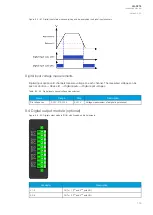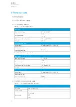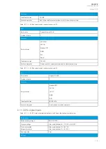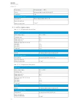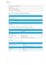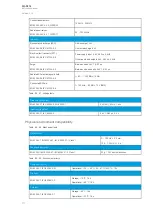
Connector
Name
Description
COM F –
Pin 1
+24 V input
Optional external auxiliary voltage for serial fiber
COM F –
Pin 2
GND
Optional external auxiliary voltage for serial fiber
COM F –
Pin 3
-
-
COM F –
Pin 4
-
-
COM F –
Pin 5
RS-232 RTS
Serial based communications
COM F –
Pin 6
RS-232 GND
Serial based communications
COM F –
Pin 7
RS-232 TX
Serial based communications
COM F –
Pin 8
RS-232 RX
Serial based communications
COM F –
Pin 9
-
-
COM F –
Pin 10
+3.3 V output
(spare)
Spare power source for external equipment (45 mA)
COM F –
Pin 11
-
-
COM F –
Pin 12
-
-
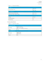
The option card includes two serial communication interfaces: COM E is a serial fiber interface with
glass/plastic option, COM F is an RS-232 interface.
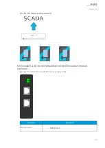
8.7 LC 100 Mbps Ethernet communication module (optional)
Figure. 8.7 - 66. LC 100 Mbps Ethernet module connectors.
A
AQ
Q-S214
-S214
Instruction manual
Version: 2.04
103
Содержание AQ-S214
Страница 1: ...AQ S214 Alarm and Indication IED Instruction manual ...
Страница 93: ...Figure 7 1 56 AQ S214 application example A AQ Q S214 S214 Instruction manual Version 2 04 92 ...
Страница 110: ...Figure 8 10 74 Device installation A AQ Q S214 S214 Instruction manual Version 2 04 109 ...
Страница 111: ...Figure 8 10 75 Panel cutout dimensions and device spacing A AQ Q S214 S214 Instruction manual Version 2 04 110 ...


