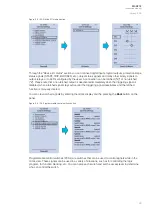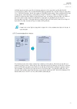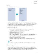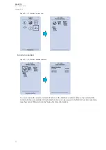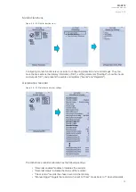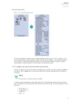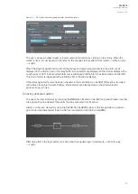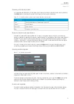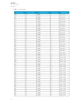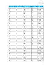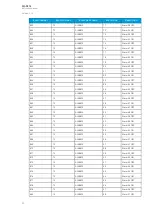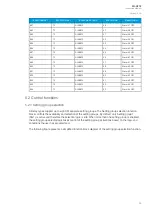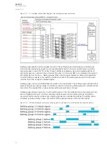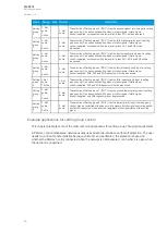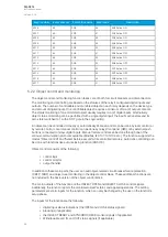
Figure. 5.1 - 38. Digital inputs assigned as alarm activating signals.
The user can assign digital inputs or logical outputs into alarms by clicking on the matrix. When the
matrix is done, it must be sent to the relay for the changes to take effect (
Commands
→
Write to relay
→
Logic).
When the signal assigned into an alarm (digital input or logical output) activates, the alarm text is
displayed in the
Alarms view in the relay's HMI. Active alarms are displayed in the Alarms display with a
continuously lit LED. A deactivated alarm text is displayed until the alarm has been cleared in the HMI.
This kind of alarm is displayed with a blinking LED in the
Alarms display.
If the alarm signal's ON state has been checked in the
Event Mask, an ALARM ON event is recorded
with a time stamp into the event history. These alarms are also reported in the communication
protocol if one is in use.
Clearing activated alarms
The user can clear all alarms by pressing the Ctrl
Ctrl button located in the IED front panel. Please note that
the signal will not be cleared if the alarm that has activated it is still active.
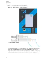
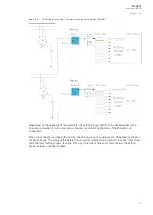
Alarms can be also cleared by using the CLEAR ALL ALARMS signal. In the image below a physical
push button activates Digital Input 4 which is connected to CLEAR ALL ALARMS.
After doing this in the logic editor, click Save and then update logic (
Commands
→
Write to relay
→
Logic).
A
AQ
Q-S214
-S214
Instruction manual
Version: 2.04
40
Содержание AQ-S214
Страница 1: ...AQ S214 Alarm and Indication IED Instruction manual ...
Страница 93: ...Figure 7 1 56 AQ S214 application example A AQ Q S214 S214 Instruction manual Version 2 04 92 ...
Страница 110: ...Figure 8 10 74 Device installation A AQ Q S214 S214 Instruction manual Version 2 04 109 ...
Страница 111: ...Figure 8 10 75 Panel cutout dimensions and device spacing A AQ Q S214 S214 Instruction manual Version 2 04 110 ...


