


3. Scan
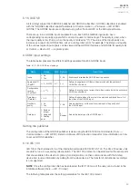
Scans Slot B, and moves to the next slot if Slot B is empty. If the scan finds an 8DI module, it
reserves the designations "DI4", "DI5", "DI6", "DI7", "DI8", "DI9", "DI10" and "DI11" to this slot. If
Slot A also has an 8DI module (and therefore has already reserved these designations), the
device reserves the designations "DI12", "DI13", "DI14", "DI15", "DI16", "DI17", "DI18" and
"DI19" to this slot. If the scan finds a 5DO module, it reserves the designations "OUT6",
"OUT7", "OUT8", "OUT9" and "OUT10" to this slot. Again, if Slot A also has a 5DO and has
therefore already reserved these designations, the device reserves the designations
"OUT11", "OUT12", "OUT13", "OUT14" and "OUT15" to this slot.
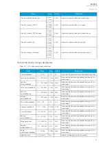
4. Scan
A similar operation to Scan 3 (checks which designations have been reserved by modules in
previous slots and numbers the new ones accordingly).
5. Scan
A similar operation to Scan 3 (checks which designations have been reserved by modules in
previous slots and numbers the new ones accordingly).
6. Scan
A similar operation to Scan 3 (checks which designations have been reserved by modules in
previous slots and numbers the new ones accordingly).
7. Scan
A similar operation to Scan 3 (checks which designations have been reserved by modules in
previous slots and numbers the new ones accordingly).
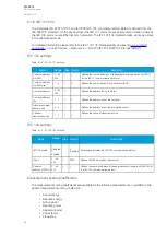
Thus far this document has only explained the installation of I/O add-on cards to the option module
slots. This is because all other module types are treated in a same way. For example, when an
additional communication port is installed into the upper port of the communication module, its
designation is Communication port 3 or higher, as Communication ports 1 and 2 already exist in the
CPU module (which is scanned, and thus designated, first). After a communication port is detected, it
is added into the device's communication space and its corresponding settings are enabled.
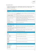
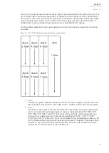
The fully optioned example case of AQ-X214-XXXXXXX-BBBBCC
BBBBCC (the first image pair, on the right)
has a total of 35 digital input channels available: three (DI1…DI3) in the CPU module, and the rest in
Slots A…D in groups of eight. It also has a total of 15 digital output channels available:
five (DO1…DO5) in the CPU module, and the rest in Slots E…F in groups of five. These same
principles apply to all non-standard configurations in the AQ-X214 IED family.
A
AQ
Q-S214
-S214
Instruction manual
Version: 2.04
95
Содержание AQ-S214
Страница 1: ...AQ S214 Alarm and Indication IED Instruction manual ...
Страница 93: ...Figure 7 1 56 AQ S214 application example A AQ Q S214 S214 Instruction manual Version 2 04 92 ...
Страница 110: ...Figure 8 10 74 Device installation A AQ Q S214 S214 Instruction manual Version 2 04 109 ...
Страница 111: ...Figure 8 10 75 Panel cutout dimensions and device spacing A AQ Q S214 S214 Instruction manual Version 2 04 110 ...


