background image


1100-2184 Rev 0 

24 

1. 

Modbus ID Auto-assign:


Automatically connect and set IDs using the integrated Magnetic Switch to pair each 
AT-G-ALERT to its install location. 

2. 

Set Modbus ID Manually:


Use the RS485 port on the controller to manually set the Modbus IDs, and then install 
according to the floorplan, while keeping track of assigned Modbus IDs. 

3.11  Method 1: Modbus ID Auto-assign 

1.  AT-G-ALERT devices can be auto-assigned their Modbus ID using a 2-person 

verification technique.  
This process gives the added advantage of physically verifying that each connected 
device is correctly installed in the assigned room location. 

2.  Open the 

Settings Screen

 (gear icon) and then enter the passcode. (If the passcode 

has not been entered, the 

Device Modbus Pairing 

Screen will not be accessible). 

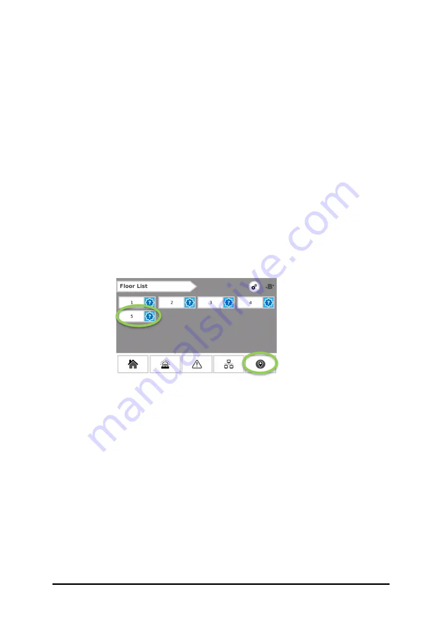
3.  On the AT-G-ALERT-C touch screen, tap the pin icon in the bottom right of the screen 

to advance to the “Floors” screen and then tap the floor that is to be commissioned. 


Figure 23 - Floor List screen 

Содержание AquiTron AT-G-ALERT-C

Страница 1: ...1100 2184 Rev 0 1...

Страница 2: ...ak Monitor 10 2 2 1 AT G ALERT C Refrigerant Leak Monitor 10 2 2 2 AT G ALERT Refrigerant Leak Detector 10 2 2 3 Ethernet Network Switch 10 2 2 4 Gateway 10 2 2 5 Modbus EZ Wire Kit 10 2 3 Hardware Ov...

Страница 3: ...tion 30 4 1 Overview of Normal Operation 30 4 2 Alarm Detection 30 4 3 Fault Detection 31 4 4 Communication Comm Error 31 4 5 Event History 33 4 6 Service Mode Screen 35 5 Additional Information 36 5...

Страница 4: ...er An imminently hazardous situation which if not avoided will result in death or serious injury Warning A potentially hazardous situation which if not avoided could result in death or serious injury...

Страница 5: ...e case of such occurrence de energize the power supply and contact Aquilar Ltd IMPORTANT Before using this product carefully read and strictly follow the instructions in the manual Ensure that all pro...

Страница 6: ...AT G ALERT refrigerant leak detectors for the following High or low PPM alarm events Hardware faults Network connectivity The AT G ALERT C controller will respond to these events as follows Alarm acti...

Страница 7: ...Status Icons Each floor and room will use the following status icons 2 1 4 Floor List Each floor will designate the highest severity status from all devices on that floor Icon Icon Name Home Alarm lis...

Страница 8: ...1100 2184 Rev 0 8 2 1 5 Room Device list each floor Detailed view for each AT G ALERT room in the system grouped on a given floor Figure 2 Floor List Figure 3 Room Device List...

Страница 9: ...tap the gear icon This screen is passcode protected to avoid unintentional changes If not already logged in the Passcode prompt will appear Enter the passcode for the AT G ALERT C controller to unloc...

Страница 10: ...for occupied rooms in applications 2 2 3 Ethernet Network Switch An Ethernet network switch is used to provide connectivity between the AT G ALERT C Controller and individual gateways 2 2 4 Gateway A...

Страница 11: ...sed alarming and monitoring for all connected AT G ALERT devices Figure 6 AT G ALERT C Overview Component Description 1 PLC Touch Screen 2 USB Port 3 Ethernet Port 4 Fault Relay 5 Alarm Relay 6 Modbus...

Страница 12: ...connect via an Ethernet TCP network through an Ethernet switch to the AT G ALERT C The AT G ALERT C provides centralized monitoring of all devices in the network with a 15 second scan rate When creat...

Страница 13: ...o eight digits of letters and or numbers It is possible to hardwire up to 15 devices to the controller s Modbus RTU port To indicate these in the floorplan fill in the cells at the bottom of the sprea...

Страница 14: ...installed 1 Open the flash drive and click the example CSV file titled data csv In this file there are columns labeled Index Floor Room Gateway ModbusID and IpAddress Of those six columns ONLY the ent...

Страница 15: ...electrical noise The AT G ALERT C will display floors listed in the order they are encountered in the spreadsheet rather than alphabetical or numeric order Every assigned room in the data csv file mu...

Страница 16: ...Download MGate Manager utility for windows from a https moxa com en products industrial edge connectivity protocol gateways modbus tcp gateways mgate mb3170 mb3270 series resources b Direct Zip downl...

Страница 17: ...this step requires a password it is moxa 6 Navigate to the Network tab the second tab Figure 15 Network tab 7 In the Network tab the IP can be set to a new value Change the IP from 192 168 0 1 to the...

Страница 18: ...8 0 1 If it is the second change the last digit to be 192 168 0 2 etc 9 Repeat this process for the remaining gateways in the system The gateways contain powerful built in troubleshooting features If...

Страница 19: ...nd responding to alarm conditions Connect the controller to a 24VDC supply capable of at least 1 Amp output WARNING Do not apply power until all wiring is in place Near to the 24V DC is a terminal blo...

Страница 20: ...ry from its contacts This plastic spacer is labelled with Pull out to activate battery If this step was skipped and a system state loss occurs after fully commissioning re upload the floorplan from th...

Страница 21: ...ay can support a maximum of 15 AT G ALERT devices connected in a daisy chain fashion using the Modbus network cable Leave no more than 30 cm for the wire tie off to each AT G ALERT The shield cable ma...

Страница 22: ...ink Here Wiring Notes The gateway provides the link between the AT G ALERT C and small groups of AT G ALERT devices up to 15 per gateway Cable type recommended Belden 3106 1 5 twisted pair shielded Da...

Страница 23: ...oller Note Instructions on filling out this spreadsheet are described earlier in this manual in Sections 3 1 and 3 2 3 Press Network Config and then press Upload CSV to upload the floorplan spreadshee...

Страница 24: ...LERT devices can be auto assigned their Modbus ID using a 2 person verification technique This process gives the added advantage of physically verifying that each connected device is correctly install...

Страница 25: ...than a second and then pull the magnetic wand away This action will put the AT G ALERT into Commissioning Mode and it should beep when the wand is being pulled away releasing Magnetic Switch A Note Op...

Страница 26: ...e has successfully commissioned a Success message will appear If the commission was unsuccessful an Unable to Contact Device message should appear and the network wiring should be checked 7 After the...

Страница 27: ...at the commission was successful 9 Repeat these steps for each room on a floor and each floor in the building until all AT G ALERT devices have been commissioned When all devices have been commissione...

Страница 28: ...e Set Modbus ID screen to select and apply a specific Modbus ID 2 Tap Search to connect to the device If the unit does not have factory Modbus ID 1 this can be restored by doing a factory reset In cas...

Страница 29: ...d Remove the magnet wand and cycle power The AT G ALERT will have reverted to default settings including default Modbus ID 1 e Specify a unique ID for the AT G ALERT this can a number 2 through 16 inc...

Страница 30: ...experiencing an alarm condition To respond to an alarm event 1 Tap Mute to silence the alarm This will mute the buzzer at the controller for 30 minutes 2 Tap Details to open the Devices in Alarm scre...

Страница 31: ...Details to open the Devices in Fault screen to view the device s impacted The Devices in Fault screen will list the Floor Room location status and network details for each AT G ALERT found to be in f...

Страница 32: ...ent 1 Tap Details to open the Comm Error screen to view the device s impacted The Comm Error screen will list the Floor Room location status and network details for each affected AT G ALERT Figure 36...

Страница 33: ...gged as neither alarm nor fault are created when a device status clears to normal Note The Fault Code is stored as a decimal value and should be converted back to a hex or binary value for easier inte...

Страница 34: ...Date Choose the date from the calendar tool on the left side of the screen and the time from the right side of the screen 4 To return to the home page press and hold the upper right corner again for 3...

Страница 35: ...r to facilitate maintenance on the network or AT G ALERT devices To access the Service Mode Screen 1 Open the Settings screen gear icon in upper right and tap the Service Mode button 2 Tap Apply to be...

Страница 36: ...d apply to this device Common household appliances can be disposed of using special collecting and recycling facilities However this device has not been registered for household usage Therefore it mus...

Отзывы: