background image

PREFACE 

IV 

Box PC BS-6500 / BS-6520 

SAFETY INSTRUCTIONS 


Failure to observe these safety instructions may cause bodily injury, or damage to the 
product. Read these instructions carefully and keep this user’s manual in an accessible 
location for future reference. 


The product may cause a fire or electric shock when it is used 
improperly. Observe the above safety measures at all times. 


If the product is damaged, immediately turn off the power and 
disconnect the power cord. Contact your dealer for assistance. 


Do not plug in or unplug the power cord with wet hands. 


Do not plug the product into an AC outlet with the incorrect voltage. 
(Be sure to use a voltage that is between AC 100V~240V) 


Do not plug several products into one multi-outlet. 


Do not apply pressure to the power cord or place heavy objects on it. 


Immediately stop using the product if it emits strange noise, odor, or smoke. 


Do not use aerosol sprayers containing flammable gas inside or around the product. 


Do not allow foreign objects or liquids to enter the product, or serious damage may 
result. 


Do not place the product on an unstable surface. The product may cause a fire if it 
is dropped, damaged, or broken. 


The following instructions will help you to make better use of this product. 


Keep the machine away from locations subject to high humidity, dust, or 
temperatures that exceed the specification. (Refer to SEC. 1.3 Specification) 


Clean the product only by using a dry cloth or a cloth soaked with detergent. Never 
use thinner or other volatile solvents for cleaning. 


At the end of the day, clean and inspect the exterior of the machine after the 
machine is powered off.   


Use only specified accessories. 


Do not expose the accessories directly to sunlight, high temperatures, humidity, 
dust, or gas. 


Do not place heavy objects on top of the product or lean them against the product. 
These items may fall down and cause injury. 


Do not block the air vent of the product as this can cause heat accumulation inside 
the box machine and may cause a fire. 


Содержание BS-6500

Страница 1: ...http www appostar com POS PC System Box PC BS 6500 BS 6520 User s Manual Edtion AUG 2012 Version 1 00...

Страница 2: ...circuit different from that to which the receiver is connected Consult the dealer or an experienced radio TV technician for help Declaration of Conformity These devices comply with part 15 of the FCC...

Страница 3: ...erves the right to improve this user s manual from time to time in the contents hereof without prior notice Copyright This work is protected by copyright laws Reproduction or retransmission of this do...

Страница 4: ...l sprayers containing flammable gas inside or around the product Do not allow foreign objects or liquids to enter the product or serious damage may result Do not place the product on an unstable surfa...

Страница 5: ...ALLATION 13 CHAPTER 3 18 SYSTEM DISASSEMBLY 18 3 1 Remove the Top Cover 18 3 2 Replacing the CPU and RAM 19 3 3 Replacing the HDD 20 3 4 Installing the PCI Expansion Card optional 21 CHAPTER 4 22 JUMP...

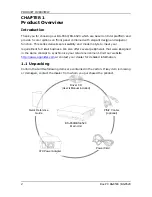
Страница 6: ...front pane rs servicea ess We a chronize y or contact g items ar ealer from User s apter BS BS 6520 w l combine ability and lso offer s your retail your deale re containe whom yo Driver CD s Manual i...

Страница 7: ...x PC B 1 2 A 1 2 1 Dimens BS 6500 B Appeara Dimen ion W x D BS 6520 ance nsion D x H 30 06 mm x 2 Wid 288 mm x dth 306 m 70 mm 1 m De PRO 12 1 x 11 epth 288 m Height ODUCT OV 3 x 2 8 mm 70 mm VERVIEW...

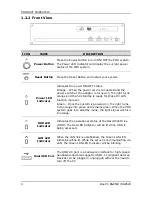
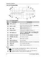
Страница 8: ...ction if preset Green Once the system is powered on the light turns from orange into green and remains green When the POS system goes into standby mode the light signal will turn to orange HDD LED Ind...

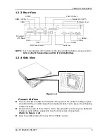
Страница 9: ...gure 1 A duct away PS 2 DIO Cash Dra informatio nnection a d on both s nts keep t more than especially from any awer Fig on on the and CH 6 sides of th them clean 5 cm for t y near hot kind of he gur...

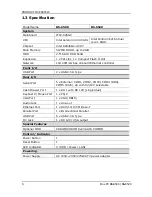
Страница 10: ...Port 2 x USB 2 0 A Type Rear I O Serial Port 5 x External COM1 COM2 COM3 COM4 DB9 COM5 RJ45 all with 5V 12V selectable Cash Drawer Port 1 x RJ11 with DC 12V single dual Keyboard Mouse Port 1 x PS 2 VG...

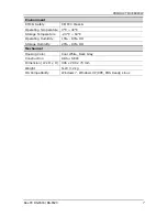
Страница 11: ...g Temperature 0 C 40 C Storage Temperature 20 C 60 C Operating Humidity 15 80 RH Storage Humidity 20 90 RH Mechanical Housing Color Cool White Dark Gray Construction ABS SECC Dimension W x D x H 306 x...

Страница 12: ...lel por nstall PCI metal cove PCI Expan DC 12V 2 5 ATX Power DB15 VGA S 2 Conne Digital I O ine out wi USB 2 0 A h LAN port er before u h DC jack emove the De with DB9 with RJ45 type Conn Connector ty...

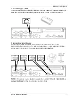
Страница 13: ...oard to this port NOTE If you would like to use mouse and keyboard simultaneously use the PS 2 Y cable supplied in the Accessory Kit See SEC 1 1 Unpacking b Connecting a Printer Connect one end of the...

Страница 14: ...rt at the BS 6500 BS 6520 and the other end to the cash drawer NOTE Check the power specification of your cash drawer first and correct the jumper setting if necessary d Connecting a Display Touch Pan...

Страница 15: ...of 0 and the on both t wer of your s for the p work func BS 6520 a ice the serial e other end he device r device is proper pow ctions Con and the ot cable to t d to the se and the B supplied b wer so...

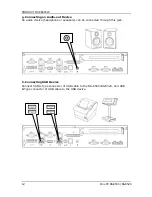
Страница 16: ...nnecting an Audio out Device An audio device headphone or speakers can be connected through this jack h Connecting USB Device Connect USB A Type connector of USB cable to the BS 6500 BS 6520 and USB B...

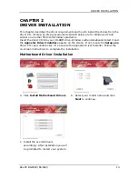
Страница 17: ...CD into your CD ROM drive Windows will automatically detect it and the Appostar Driver Installer appears on the screen If not locate the Setup exe file at CD and double click it to execute the Apposta...

Страница 18: ...l Chipset Driver 2 Follow the on screen instructions to complete the installation d Click Next on the Welcome screen to continue e Click Yes on the License Agreement screen to continue f Click Next on...

Страница 19: ...iver 2 Follow the following instructions to complete the installation a Select English as setup language and click Next to continue b Click Next to continue c Click Install to begin the installation d...

Страница 20: ...rnet Driver 2 Follow the on screen instructions to complete the installation a A Preparing Setup window appears Please wait b Click Next on the Welcome screen to continue c Click Install to begin the...

Страница 21: ...nstall Audio Driver 2 Follow the on screen instructions to complete the installation a Click Next on the Welcome screen to continue b A progress window appears Please wait c An Installing window pops...

Страница 22: ...function of the BS 6500 or peripheral devices Before You Begin Be sure to have a stable clean working environment Keep all small components in a safe container to prevent them from getting lost Discon...

Страница 23: ...et lat ace Open RAM chip op cover w CPU an op cover lo a CPU is t r upwards tch The la the clips f securely in with 3 scre nd RAM Fig Fig Fig ocate the C o unscrew and repla atch will be for the rep n...

Страница 24: ...4 mounting screws that hold the HDD bracket in place inside the case and disconnect SATA 1 and SATA power cables from HDD b Unfasten 4 screws from the HDD bracket to replace the HDD with a new one Rei...

Страница 25: ...ved the to e PCI meta xpansion C ser Card i w into the P nsion Card op cover al cover th Card into t nto the PC PCI metal d optiona Fig Fig locate the at holds t he PCI Ris CI Expansi cover and al g 3...

Страница 26: ...n board is configured properly Main Board of BS 6500 Jumper Allocation Jumper Function Jumper Function JP1 COM1 RI Function Selection JP7 COM2 RI Function Selection JP2 Panel Mode Selection JP8 COM4 R...

Страница 27: ...n Jumper OPEN If without the jumper cap or the jumper cap only placed on one pin the jumper is OPEN 3 pin Jumper Jumper Block Jumper Cap SHORT When the jumper cap is placed on both pins the jumper is...

Страница 28: ...In 5 6 short 12V JP4 COM5 Mode Selection JP4 Mode 1 2 3 5 4 6 short RS232 Mode 1 1 3 2 4 short RS232 Mode 2 JP5 COM3 RI Function Selection JP5 Function 1 2 short 5V 3 4 short Ring In 5 6 short 12V JP...

Страница 29: ...1 2 3 4 open RS232 Mode 2 JP10 CMOS Clear JP10 Function 1 2 Short Normal Operation 2 3 Short Clear CMOS Contents JP11 Compact Flash Master Slave Selection JP11 Function 1 2 Compact Flash set to Maste...

Страница 30: ...ON The term I O Input Output is used to describe any device that transfers data from to the computer to from peripheral devices Check the following sections to verify the connector allocation and its...

Страница 31: ...INV1 LVDS Inverter Power Connector LVDS1 LVDS LCD Panel Connector JFront1 Front Panel Connector LAN RJ45 LAN Connector LPT Parallel port with D sub 25 Pin SATA1 SATA2 SATA Connector SATA_PWR1 SATA Po...

Страница 32: ...rite 11 Ground 36 Pull Up to 5V 12 Ground 37 IRQ 15 13 5V 38 5V 14 Ground 39 Slave Master Select 15 Ground 40 N C 16 Ground 41 Reset 17 Ground 42 IORDY 18 SA2 43 DMA REQ 19 SA1 44 DMA ACK 20 SA0 45 ID...

Страница 33: ...ption 1 DCD 2 DSR 3 RXD 4 RTS 5 TXD 6 CTS 7 DTR 8 RI 5V 12V 9 Ground 10 RI 5V 12V KB MS PS2 Keyboard Mouse with Mini DIN Connector PIN No Signal Description PIN No Signal Description 1 KBDATA 2 MSDATA...

Страница 34: ...HDD LED 9 Ground 10 Reset Switch DIO1 DIO Connector with Pin Header 2 54 mm PIN No Signal Description 1 DIO In 2 DIO Out LVDS1 LVDS Panel Signals with Wafer Connector 1 0 mm PIN No Signal Description...

Страница 35: ...4 19 Ground 7 Data 5 20 Ground 8 Data 6 21 Ground 9 Data 7 22 Ground 10 Acknowledge low 23 Ground 11 Busy 24 Ground 12 Paper Empty 25 Ground 13 Printer Select SATA1 2 SATA Connector PIN No Signal Des...

Страница 36: ...n U1 5V U5 5V U2 USBDATA0 U6 USBDATA1 U3 USBDATA0 U7 USBDATA1 U4 Ground U8 Ground L1 TXD L5 NC L2 TXD L6 RXD L3 RXD L7 NC L4 NC L8 NC USB2_COM5 USB 3 4 Connector COM5 with Dual USB RJ 45 PIN No Signal...

Страница 37: ...l Description 1 USB 5V 2 USB 5V 3 USBDATA6 4 USBDATA7 5 USBDATA6 6 USBDATA7 7 USB Ground 8 USB Ground VGA Monitor Connector with D Sub 15P PIN No Signal Description PIN No Signal Description 1 RED 2 G...

Страница 38: ...ing connected Refer to SEC 1 2 2 Front View Make sure that all cables between the wall outlet and the product are firmly connected Peripheral Device Does Not Work Make sure that all cable connections...

Страница 39: ...crews from op cover PCI Ex CI metal c CI expans CI riser ca efer to the e instructio Slot er ver m the pansion cover ion card in ard into th e SEC 3 4 ons PCI Ri Ste Pu top n Card nto the PC e PCI ex...

Отзывы: