background image

7.2.1 Volt Setting & Measurement Calibration

This item is for calibrating the voltage setting and measurement. Make sure to disconnect the

Resistive load before starting calibration.

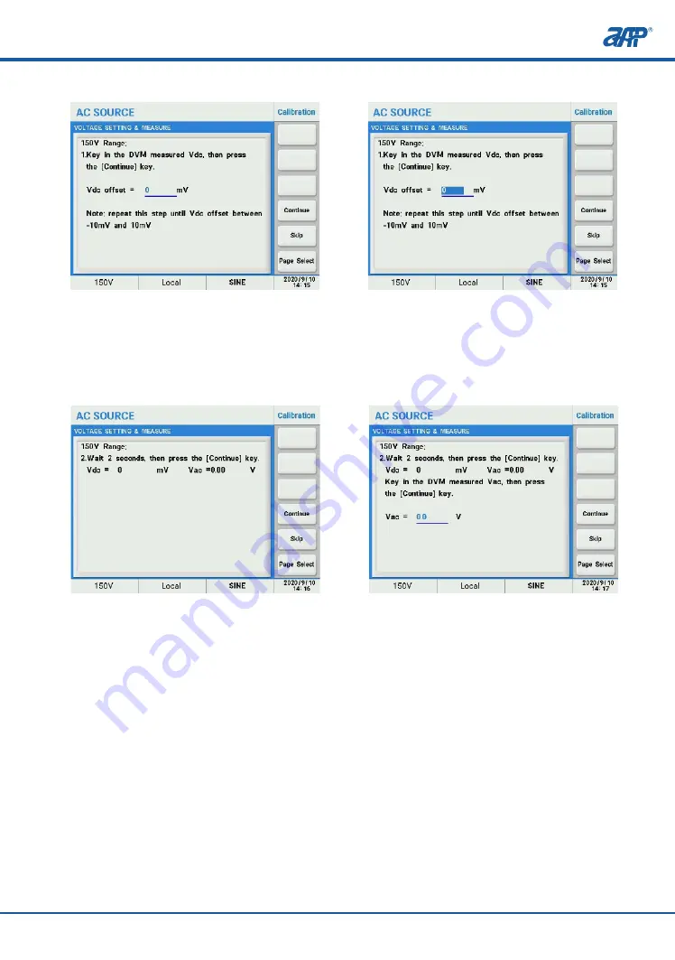
1. Once the password has been entered press the soft key to the right of ‘Volt Setting & Measure’.

2. You will enter into the 150V Range voltage calibration. Make sure there is NO Load at the

    output. Then press the ‘Continue’ soft key for the next step.

3. Highlight the value field and enter the DVM DC voltage reading and repeat this step until 

    the DVM reading is between -10mV and 10mV.


Calibration

94

PROFESSIONAL    INNOVATIVE    BRANDING    SERVICE

4. Wait 2 seconds then press the ‘Continue’ key.

5.  Highlight the value field and enter the DVM AC voltage reading then press the ‘Continue’ 

    soft key for the next step.

Follow the on-screen prompts to complete calibration the 150V AC range. Both AC & DC output

and AC & DC measurements are calibrated.

Once completed, repeat the same process for the 300V AC range.

7.2.2 Current Measurement Calibration

This menu is for calibration of the power source’s current measurement functions. The power

source uses up  to  four  measurement ranges depending  on  models. Each range has two 

calibration coefficients. 

Follow the on-screen prompts to complete the complete calibration sequence for all ranges 

and coefficients.

Calibration

95

PROFESSIONAL    INNOVATIVE    BRANDING    SERVICE

Содержание SP-300 Series

Страница 1: ...APM TECHNOLOGIES PROFESSIONAL INNOVATIVE BRANDING SERVICE SP 300 Series Single phase Programmable AC Power Supply en apmtech cn User Manual...

Страница 2: ......

Страница 3: ...pair 8 3 Products Introduction 8 3 1 Product Description 8 3 2 Product Features 9 3 3 Operation Instructions 10 3 4 Operation Environments 10 3 5 Maintenance and Cleaning 10 3 6 Product Storage 11 3 7...

Страница 4: ...Limitation Setting 32 5 2 2 Menu Setting 33 5 2 2 1 Config Setting 33 5 2 2 2 LCD Setting 41 5 2 2 3 Calibration 43 5 2 2 4 Other Setting 43 5 2 3 Output Mode 44 5 2 3 1 PLD Testing 44 5 2 3 2 Harmon...

Страница 5: ...2 2 4 I Range High DC High Current Coefficient 97 7 2 3 Saving Calibration Coefficient 98 8 Installation 99 8 1 Product Dimensions 99 8 2 Installing Rack Mount Handles 100 8 3 Installing the Optional...

Страница 6: ...15 1200Hz 2 IEC 61000 4 11 IEC 61000 4 11 IEC 61000 4 14 IEC 61000 4 28 IEC 61000 4 13 IEC 61000 3 2 IEC 61000 3 3 3 4 5 Remote I O Parallel Multiphase Link Card 6 GPIB communication interface Output...

Страница 7: ...s symbol indicates of high voltage risk aspects of the product or its use This symbol indicates parts that may be at a high temperature Please do not touch this part of the equipment to prevent scaldi...

Страница 8: ...ee of electrical and mechanical knowledge and be familiar with basic electrical and mechanical schematics All materials including but not limited to graphics logos symbols data etc in this manual are...

Страница 9: ...Cable DVI BNC Cable Quick Guide As ordered Standard Standard Standard Fasten item B Standard Standard Standard Standard Optional Optional Optional English Version Descriptions Item A B C D E F G H I...

Страница 10: ...re If the power source requires repairing at the factory or repair center please pack it in the original packing material Please assure to contact APM to receive prior authorization for the product re...

Страница 11: ...n output metering capable of measuring 15 electrical parameters including output voltage current frequency etc Suitable for IEC 61000 3 2 and IEC 61000 3 2 tests The product includes comprehensive mea...

Страница 12: ...at 30 cm of space is present at the front and back of the unit Internal fans cool the power source by drawing air through the front and exhausting it out the back 4 Do not operate this product in an e...

Страница 13: ...rce is deactivated prior to making or disconnecting the connection 3 8 Fuse The input AC fuses installed inside the product are designed to protect the units input from major component failures and th...

Страница 14: ...Extern EEPROM Check checks the external EEPROM memory if failed shows as FAIL Extern RAM Check checks the external RAM memory if failed shows as FAIL Parallel Board Check checks whether remote I O and...

Страница 15: ...anel Description Panel Description 1 4 13 Panel Description Front Panel of 2U Models Front Panel of 3U Models Front Panel of 4U Models 1 2 4 5 6 9 8 3 7 1 2 3 4 5 6 7 8 9 PROFESSIONAL INNOVATIVE BRAND...

Страница 16: ...to the Main screen To turn the output of AC source On or Off Press to lock the front panel keys This shift key is used to select the alternate operation of a key indicated by the word under the key S...

Страница 17: ...Enter Keys Name and the function Manual Reference Recall the setup from internal memory Store the settings in non volatile memory Up Left key Down Right key Confirm key 4 2 Rear Panel Description 1 AC...

Страница 18: ...0 0 5V 1 High 4 5 5 5V 0 Low 0 0 5V 1 High 4 5 5 5V 0 Low 0 0 5V 1 High 4 5 5 5V Not Used GND ON OFF 1 KEEP OFF RESET CALL 1 CALL 2 CALL 3 N A EXT V Pin 1 2 These two pins will connected internally wh...

Страница 19: ...optional Input terminals Interface Description SYNC CAN R SYSTEM BUS TTL ANALOG Used for communication between master and slaves TTL signal analog input interface Refer to P18 for details Connect CAN...

Страница 20: ...de Store Recall Parallel Series 3 Phase Lock Setting Output More Setting Measure Setting Waveform Viewer Limitation Coupling Range Waveform Preview Zo Program Waveform A B ON OFF Degree Vac S R Vdc S...

Страница 21: ...Mode Config Menu LCD Setting Display Date Time Screen Calibration Screen Color Test Remote Control System Setting System Information External Control Protection Calibration Other Recall Default Warni...

Страница 22: ...tion mode 4 Under remote operation mode all Front Panel keys except the decimal point key are locked On Off 5 1 3 Key Operations and Touch Screen Operations Voltage setting Option one using front pane...

Страница 23: ...ayed press the Enter key to confirm Option two using touch screen 1 Touch the desired value area a small keyboard will be displayed as shown below 2 Touch the numeric keys 0 9 as desired then touch th...

Страница 24: ...key to highlight AC DC option then press the Enter key to confirm OR 3 Scroll knob to highlight AC DC option then press the knob to confirm Option two using touch screen 1 Touch the Coupling soft key...

Страница 25: ...keys as touch screen operation is self explanatory The following Soft Keys are available in the Setting screen to access these setup screens 5 2 1 1 Output More Setting This screen allows control over...

Страница 26: ...utput mode of the AC source including AC DC and AC DC modes For example to set Coupling as AC DC 2 Range This menu is for setting the output range of the AC source which includes Low Range 150 High ra...

Страница 27: ...switchover of range Range setting will be always display on the lower left conner of the display 3 Waveform Generators The AC source provides the user with two independent waveform generators A and B...

Страница 28: ...keys to confirm 2 Move the cursor to highlight OFF Degree field press the Enter key to change to settable status then press the 9 0 and Enter keys to confirm 5 Slew Rate Setting This item is for sett...

Страница 29: ...an be inferred however from the waveform cycle and frequency setting Note 7 Zo Program This item is for setting the internal output impedance Zo which consists of simulated output resistance R and ind...

Страница 30: ...mH If L is more than 0 5 mH and the output voltage is low e g less than 100Vac any large load current may cause an unstable output voltage It is important that the user adjusts the L value slowly whi...

Страница 31: ...in amps Idc DC output current measured in amps Ipk Peak peak output current measured in amps Is surge current measured in amps F the output frequency measured in Hz PF output power factor PF P VA CF c...

Страница 32: ...I Range 2 Rotate knob to highlight Low and press the Enter key to confirm Note The Auto range selection will only switched between High and Middle range To change settings between High Middle and Low...

Страница 33: ...2 Press 1 0 and then Enter keys to confirm 2 I Average The Average soft key changes the number of times a reading is averaged before the corres ponding measurement parameter display is updated Availa...

Страница 34: ...s are useful to protect a unit under test from operator error by setting upper and or lower parameter value limits for key output parameters like voltage and frequency Vac range is 0 300V F range is 1...

Страница 35: ...5 2 2 1 Config Setting The Config screen controls the following aspects of the power source Remote Control System Setting System Information External Control Protection 1 Remote Control 1 1 RS232 The...

Страница 36: ...485 settings 2 Move the cursor to highlight 485 Addr field then press 5 and Enter keys to confirm 1 In the Remote Control menu press the RS232 soft key to change RS 232 interface settings 2 Move the c...

Страница 37: ...Setting field press the Enter key to confirm 3 Rotate the front panel knob to highlight the Manual item press the Enter key to confirm 4 Move the cursor to highlight the setting area and press 0 9 an...

Страница 38: ...ple to set Buzzer to OFF 1 In the System Setting menu press the Buzzer soft key to change the state of the buzzer 2 Rotate the front panel knob to highlight the OFF option then press the Enter key to...

Страница 39: ...setup can be assigned for recall when the power source is turned on For example to set P O State as USER Couple set as AC DC Vac set as 100V F set as 50 Hz and Vdc set as 20V 1 In the System Setting m...

Страница 40: ...to OFF the output relay will close when the output state is ON and open when the output state is OFF This is normal operation for most power sources and should be the default setting For example to se...

Страница 41: ...V Range Vout dc Vref dc 3 Vdc x 424 2 Vdc 150V Range Vout dc Vref dc 3 Vdc x 212 1 Vdc 4 External Control The AC source allows the user to make use of a controlling signal from external devices to det...

Страница 42: ...range is from 0 through 1 02 times of rated current OCP Delay setting range is from 0 through 5s CC constant current Mode in this mode the output voltage will be automatically decreased to limit the...

Страница 43: ...en Calibration Screen Color Test If the output power is 1 1 1 times of the OPP setting the output will shut down in about 10s If the output power greater than 1 1 times of the OPP setting the output w...

Страница 44: ...time of shipment but will have to be adjusted for local date and time zone 1 In the LCD setting screen press the soft key to the right of Date Time 2 Move the cursor to highlight the item of year mon...

Страница 45: ...so will erase the current setup and replace it with default values 1 Recall Default 1 Press the soft key to the right side of Recall Default 2 Press the Yes soft key to restore the factory default set...

Страница 46: ...The unit supports three transient modes List Mode Pulse Mode Step Mode 3 License Displays license information 5 2 3 Output Mode The following items can be configured from this screen PLD Testing Harmo...

Страница 47: ...vailable characters include A Z 0 9 and blank Then press the Enter key to confirm 4 With the desired List highlighted press the soft key to the right of Edit to edit or create the list file using the...

Страница 48: ...If the running mode is set as Step the output will remain as the end waveform until the Trigger soft key is touched again The parameters in list files are limited to the limit settings as programmed u...

Страница 49: ...he time period to hold the present output set values before starting the pulse period s Save to save the settings to an assigned memory location for quickly recalling at a later time If you do not sav...

Страница 50: ...he Step Mode soft key 2 Press the Edit soft key 3 Press the ESC key to return to the previous screen then press the Trigger soft key to load the settings 4 Press the Trigger soft key to execute the fi...

Страница 51: ...ics Harmonic Measure User Power Sweep sweep function Save to save setting to assigned memory room for quickly recall at any time Do not save the setting after power off the unit current file will lose...

Страница 52: ...ngs to the assigned memory location for quickly recalling at a later time If you do not save the current Synthesis settings file it will be lost after the unit is turned off The waveform synthesis scr...

Страница 53: ...ue 45V or the Percent 15 An OVP error is generated if the output of the synthesized waveform DC offset exceeds 424Vpk on the 300V range or 212Vpk on the 150V range 3 Press the ESC key to return to the...

Страница 54: ...uency component sweep at the output at a fre quency that is not harmonically related to the fundamental frequency This function is useful for performing immunity tests 2 Inter harmonics 1 Press the In...

Страница 55: ...oft key 2 Press the Edit soft key enter the desired source values as follows Source select V or I to measure voltage or current F_fund 50Hz or 60Hz TIMES Single or Continue Single means one measuremen...

Страница 56: ...1 Press the User soft key 2 Move the cursor to highlight User NO field then press the appropriate numeric key and then Enter key to confirm Use the front panel knob to the desired waveform harmonics...

Страница 57: ...waveform settings to the assigned memory location for quickly recalling at a later time If you do not save the current User file it will be lost after the unit is turned off The user can recall the u...

Страница 58: ...61000 4 11 These test items parameters can also be user defined 1 IEC 4 11 1 In the IEC standards screen press the IEC 4 11 soft key 2 Press the Voltage Dips soft key 3 Press the Edit soft key 4 Move...

Страница 59: ...Frequency field then press the Enter key to switch between 50 and 60 Step test step number value in of Unom Cycle the duration of the dip expressed in cycles Start Degree start angle of the dip 0 359...

Страница 60: ...previous screen then press the Load soft key to load the settings 11 Press the Trigger soft key to execute the file and the Trigger will change to Stop Voltage Variations Settings 1 In the IEC standa...

Страница 61: ...uns in an infinite loop 1 count Voltage variations Interval Unom fixed to 230V in Standard mode can be set as desired in User Def mode Frequency fixed to 50Hz or 60Hz in Standard mode td fall time for...

Страница 62: ...ms parameters also can be user defined 2 IEC 4 13 1 In the IEC standards screen press the IEC 4 13 soft key 2 Press the Flat Curve soft key Flat Curve Setting 60 5 Press the Diagram soft key to previe...

Страница 63: ...odes Test Time Duration of test 3 Press the Edit soft key 4 Move the cursor to highlight Test Level field then press the Enter key to display the drop down list 5 Rotate the front panel knob to highli...

Страница 64: ...non volatile memory 8 Press the ESC key to return to the previous screen then press the Trigger soft key to load the settings 9 Press the Trigger soft key to execute the file and the Trigger will chan...

Страница 65: ...t for 3rd and 5th harmonics Harmonics Phase phase shift of third and fifth harmonics 3 Press the Edit soft key 4 Move the cursor to highlight Test Level field then press the Enter key to display the d...

Страница 66: ...r key to display the drop down list 5 Rotate the front panel knob to highlight non multiple of 3 and press the Enter key to con firm 64 The test time now run until completed Total test time is determi...

Страница 67: ...ng a test run 65 6 Move the cursor to highlight Level field then press the Enter key to display the drop down List 7 Rotate the front panel knob to highlight Class 2 and press the Enter key to confirm...

Страница 68: ...Setting 3 Press the Edit soft key to set the required test selections for this test 4 Move the cursor to highlight Level field and press the Enter key to display a drop down list with product class se...

Страница 69: ...ns 6 Press the Save soft key to store the settings in non volatile memory 7 Press the Trigger soft key to execute the file Once pressed it changes to Stop 67 The test time now run until completed Tota...

Страница 70: ...in Frequency Setting 3 Press the Edit soft key to set the required test selections for this test 4 Move the cursor to highlight the Level field and press the Enter key to display a drop down list with...

Страница 71: ...ss the Edit soft key 4 Move the cursor to highlight Level field then press the Enter key to display the drop down list 5 Rotate the front panel knob to highlight Class 2 then press the Enter key to co...

Страница 72: ...4500 f Default test levels Unom for 50Hz mains 70 Unom Nominal test voltage fixed to 230V in standard modes Frequency 50Hz or 60Hz in standard modes Test Levels in of Unom for Inter Harmonics ranges...

Страница 73: ...ield then press the Enter key to switch between Standard and User Def 4 Move the cursor to highlight Class field then press the Enter key to display the drop down list rotate the front panel knob to h...

Страница 74: ...ameters also can be user defined 4 IEC 4 28 1 In the IEC standards screen press the soft key to the right of IEC 4 28 2 Press the soft key to the right of Edit 72 5 Press the Diagram soft key to see a...

Страница 75: ...wn list rotate the front panel knob to highlight Level 2 and press the Enter key to confirm Unom nominal test voltage fixed at 230V in Standard mode can be edited in User Def mode Frequency fixed at 5...

Страница 76: ...review 6 Press the Save soft key to store the test setting in non volatile memory 7 Press the ESC key to return to the previous screen then press the Trigger soft key to load the settings 8 Press the...

Страница 77: ...oltage of the transient s detailed information refer to Appendix A Trans Time to set the duration of the transient s Trans Count to set the number of times the transient is repeated 3 Press the Save s...

Страница 78: ...Dimmer function to regulate the active power thus adjusting the lighting intensity in the case of a luminary load 2 Triac Dimmer 1 Press the Triac Dimmer soft key to select the Triac Dimmer test mode...

Страница 79: ...the Trigger key to load the settings 5 Press the Trigger soft key to apply the test to the unit under test Once pressed it changes to Stop 5 2 3 5 Test Mode This menu provides users a function to comp...

Страница 80: ...ress the Test Mode soft key to enter limit test mode 2 Press the Save soft key to save the settings to non volatile memory Note If the remote I O Parallel Multiphase Link Card has been connected the t...

Страница 81: ...Channel field located in the middle of the screen Use 0 9 keys to select a channel number from 1 through 51 and press Enter key to save the output settings to this Channel register 3 To recall the ou...

Страница 82: ...to the Group field located in the middle of the screen Use 0 9 keys to select a group number from 1 through 9 and press Enter key to save the system settings to this group register 3 To recall the sy...

Страница 83: ...rce configuration To lock the front panel keys and touch screen from the Main Page screen press the soft key to the right of Lock A lock sign will be displayed on the bottom right of the screen Press...

Страница 84: ...ster slave mode Set up all Slave units first then set up the Master in Master Slave configuration There can only be ONE Master unit in any Master Slave configuration Each Slave unit s number Must be u...

Страница 85: ...ay the saved state of this unit 7 Press the Save soft key to store the master slave mode setting to non volatile memory Warning The Slave units can be unlocked by pressing the key on the front panel N...

Страница 86: ...r to highlight the right option and press the Enter key to confirm 84 7 Press the Load soft key to recall and display the saved state of this unit 8 Press the Save soft key to store the master slave m...

Страница 87: ...nit as Parallel then press the Main key switch to main menu Parallel connection 1 2 3 Output connection Termination resistor CAN R flip Dip Switch 1 of the Master unit to ON position down System Bus C...

Страница 88: ...in key to return to the main page Series connection 1 2 3 Output connection Termination resistor CAN R flip Dip Switch 1 of the Master unit to ON position down System Bus Communication Cable L N 1 2 3...

Страница 89: ...ttings as that for phase A automatically if the Voltage Mode is set to COM If the Voltage Mode is set to Multi phase B and C output voltage can be set individually The output frequency of phase B and...

Страница 90: ...Main page 88 Master slave Mode Operation PROFESSIONAL INNOVATIVE BRANDING SERVICE...

Страница 91: ...ge is 0 300V B 1 2 3 ON A C N G L1 L2 L3 N 1 2 3 4 1 2 3 4 Output connection Termination resistor CAN R flip Dip Switch 1 of the Master unit to ON position down System Bus Communication Cable Only sup...

Страница 92: ...A C G L1 L2 L3 N 1 2 3 4 1 2 3 4 Output connection Termination resistor CAN R flip Dip Switch 1 of the Master unit to ON position System Bus Communication Cable Only support three phase five wire inpu...

Страница 93: ...an display Yes Yes Yes Not Supported Yes Yes Yes Yes Yes Yes Not Supported Not Supported Applies to phase A only Phase B C will be shifted 120 240 On Degree 1 Soft Start Off Degree Coupling Range Wave...

Страница 94: ...ed Yes Yes Yes 1 Soft Start includes Vac S R Vdc S R and F S R setting 2 O P Relay function set as ON only available in single mode 3 Calibration function only available for single unit 4 Harmonics fu...

Страница 95: ...0Vac RMS minimum 2 Calibrated traceable 4 1 2 digit digital ammeter DAM 25A RMS minimum 3 Suitably rated Resistive Load 240V minimum 7 1 Calibration Equipment Required AC Source to be calibrated R Loa...

Страница 96: ...en entered press the soft key to the right of Volt Setting Measure 2 You will enter into the 150V Range voltage calibration Make sure there is NO Load at the output Then press the Continue soft key fo...

Страница 97: ...are calibrated Once completed repeat the same process for the 300V AC range 7 2 2 Current Measurement Calibration This menu is for calibration of the power source s current measurement functions The p...

Страница 98: ...y to the right of Current Measure 7 2 2 2 I Range High AC High Current Coefficient The next calibration point is for high AC current measurements Adjust the load to 24 Aac Note Depending on the power...

Страница 99: ...DAM When done press the Continue key to the next calibration coefficient 1 Adjust the load setting for a current of 24 Aac 10 2 Highlight the Measured I field value then enter the current reading from...

Страница 100: ...te It is possible to skip any coefficient by press the Skip soft key if calibration is deemed but it is better to follow the prompt messages provided on the display step by step 7 2 3 Saving Calibrati...

Страница 101: ...0 483 0 8 1 Product Dimensions Installation 1 8 Note refer to Appendix A to get the detailed information of the dimensions of the power sources 99 Dimensions of 4U Models Dimensions of 3U Models PROF...

Страница 102: ...fix the unit in the rack instead of carrying the unit 8 3 Installing the Optional Cards This series AC source provides optional interface cards The interface slot is located on the rear panel making...

Страница 103: ...I O Parallel Multiphase Link Card GPIB Communication Card This series AC source provides optional interface cards The interface slot is located on the rear panel making it easy for the user to plug a...

Страница 104: ...al of the AC Power input terminal block to earth ground otherwise an electric shock hazard may exist There is certain danger if the connection of AC power source is not done properly please assure tha...

Страница 105: ...through the cable clamp and nut according to the direction of the drawing below and then insert it into the line neutral and ground terminals resp ectively 4 Using a suitably sized flat blade screwdri...

Страница 106: ...minal bock assuring the wires are held tightly 5 Replace and fasten the terminal cover box and tighten the plastic nut of the cable strain relief clamp Model Wire Size SP300VAC600W SP300VAC1500W 2 1 6...

Страница 107: ...d currents short connections to the load or where the load regulation is less critical 2 Remote sensing refer to figure b Use remote sensing in application where load regulation at the load is critica...

Страница 108: ...e AC input to ensure the voltage can meet the requirement The screen shows the message C005 BUS_UVP Bus over current Ask your agent for help The screen shows the message C006 USB_OCP USB over current...

Страница 109: ...t wires are short circuited or the load connected to the power are short circuited Turn off the output and check the cables to ensure they are properly connected before turning the power back on The s...

Страница 110: ...product properly Contact Us 1 11 If you have any questions about the SP 300 Series Programmable AC Power Supply please contact us We will be happy to answer any of your questions Below are our contac...

Страница 111: ...Regulation Rise Fall Time DC 6 0 1 F S 15 70Hz Resistive Load 0 5 F S Others Freq Resistive Load 0 1V 250us 0 5 Resistive Load at 15 0 70 0Hz and output voltage within 80 140VAC at Low Range or 160 2...

Страница 112: ...d value Signal ON OFF RESET KEEP OFF Recall program memory 1 through 7 Signal output indicating that a test mode is present Signal PASS FAIL TEST IN PROCESS Signal input for output voltage waveform pr...

Страница 113: ...nding Range Resolution Accuracy Range Resolution Accuracy Max Power Max Current L H Range Ripple Noise r m s Ripple Noise Peak Voltage DC Current CC Fold Mode Resolution Accuracy Response Time Frequen...

Страница 114: ...standard as required for EU CE Mark FCC Verification of conformity for CFR 47 Part 15 of the FCC Rules CE marked for LVD Directive 2014 35 EU EN61010 1 third edition as required for EU CE Mark Instal...

Страница 115: ...BRANDING SERVICE Appendix B Fixed Waveform FIXED NO 0 Harmonic 5 7 8 9 8 15 8 2 16 0 0 0 FIXED NO 1 Harmonic 3 7 19 1 44 1 47 1 95 0 0 0 FIXED NO 2 Harmonic 3 5 7 23 31 1 96 1 37 1 98 1 42 1 0 0 0 0...

Страница 116: ...NNOVATIVE BRANDING SERVICE FIXED NO 3 Harmonic 3 5 7 23 25 31 33 2 45 1 88 2 46 1 95 1 09 1 52 1 09 0 0 0 0 0 0 0 FIXED NO 4 Harmonic 3 5 7 9 11 1 00 2 75 1 35 2 25 1 45 0 0 0 0 0 FIXED NO 5 Harmonic...

Страница 117: ...armonic 3 5 7 9 11 15 21 2 17 5 59 2 79 4 58 2 92 1 35 0 99 0 0 0 0 0 0 0 FIXED NO 7 Harmonic 3 5 7 11 15 17 4 86 1 58 2 64 1 37 1 95 1 06 0 0 0 0 0 0 FIXED NO 8 Harmonic 3 5 7 11 13 15 7 27 2 39 4 01...

Страница 118: ...NAL INNOVATIVE BRANDING SERVICE FIXED NO 9 Harmonic 3 5 7 9 11 13 9 78 3 19 5 37 1 17 2 76 1 37 0 0 0 0 0 0 Harmonic 15 17 19 21 23 25 3 92 2 13 1 34 1 39 1 59 1 36 0 0 0 0 0 0 FIXED NO 10 Harmonic 3...

Страница 119: ...endix B Fixed Waveform 117 PROFESSIONAL INNOVATIVE BRANDING SERVICE FIXED NO 12 Harmonic 3 24 48 0 FIXED NO 13 Harmonic 2 5 7 2 19 9 83 15 76 0 0 0 FIXED NO 14 Harmonic 2 5 7 8 1 04 4 9 7 86 1 14 0 0...

Страница 120: ...ix B Fixed Waveform 118 PROFESSIONAL INNOVATIVE BRANDING SERVICE FIXED NO 15 Harmonic 5 7 2 42 3 91 0 0 FIXED NO 16 Harmonic 3 5 7 9 11 08 4 05 2 03 1 27 180 0 180 0 FIXED NO 17 Harmonic 3 5 7 16 3 46...

Страница 121: ...TIVE BRANDING SERVICE FIXED NO 18 Harmonic 3 5 9 13 8 07 3 55 0 96 0 92 0 180 0 180 FIXED NO 19 Harmonic 3 5 9 13 9 38 3 44 1 12 0 5 0 180 0 180 FIXED NO 20 Harmonic 3 5 7 9 11 13 23 25 2 06 1 77 1 62...

Страница 122: ...5 7 9 11 13 0 13 4 28 3 77 3 27 2 57 1 93 1 22 180 180 0 180 0 180 0 FIXED NO 23 Harmonic 3 5 7 9 11 13 15 5 74 5 11 4 44 3 52 2 63 1 65 0 8 180 0 180 0 180 0 180 Harmonic 21 23 25 27 29 0 62 0 73 0 7...

Страница 123: ...6 6 5 74 4 57 3 41 2 16 1 04 180 0 180 0 180 0 180 FIXED NO 26 Harmonic 21 23 25 1 24 4 91 2 21 0 0 0 Harmonic 19 21 23 25 27 29 0 74 1 35 1 64 1 73 1 56 1 24 0 180 0 180 0 180 FIXED NO 25 Harmonic 5...

Страница 124: ...28 Harmonic 3 5 7 9 11 13 15 17 19 21 33 39 20 01 13 75 10 71 8 37 7 05 5 84 4 84 4 83 4 48 0 0 0 0 0 0 0 0 0 0 FIXED NO 29 Harmonic 3 5 7 9 11 13 15 33 39 20 01 13 74 10 67 8 33 6 99 5 26 0 0 0 0 0...

Страница 125: ...ated below Please read the following instructions carefully This warranty is applicable to the Programmable AC Power Source of APM All quality warranties and services offered by your distributors are...

Страница 126: ...nvironment that is beyond the limitations specified in this product manual 7 Defects or damages caused by or resulting from failure to comply with the operating instru ctions and contents specified in...

Страница 127: ...your product and to put warranty coverage in force 4 Should any malfunction of product occurs please contact your installer distributor or dealer timely so as for us to provide you with corresponding...

Страница 128: ...on Product Malfunction Information Company Name Contact Person Phone Code Address Name Phone Code Address Fax E mail Model Serial No Warranty Period Date of Malfunction Signature Malfunction Descripti...

Страница 129: ......

Страница 130: ......

Страница 131: ......

Страница 132: ...Tel 86 769 2202 8588 E mail overseas apmtech cn Fax 86 769 2202 6771 Web en apmtech cn Add 7 Link Information Industry Park Shuilianshan Road Nancheng Dongguan Guangdong China...

Отзывы: