NEO
fl
o
Water
Heater
24
September
2015
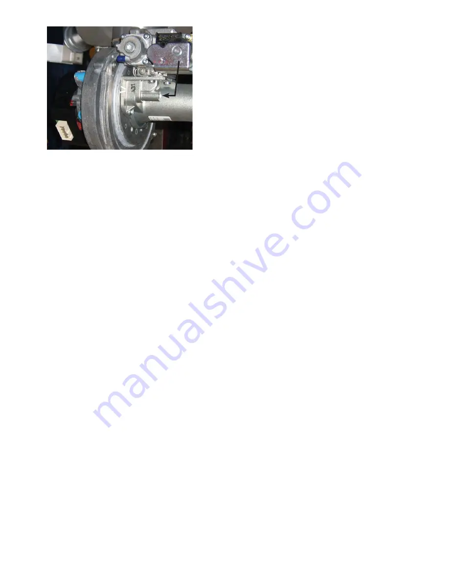
Fig 9.1
PRESSURE TEMPERATURE RELIEF VALVE
(Fig. 2.1)
Th
e removal of this valve will require either the draining
or the valving-off of the system that is above tank level.
•
Undo the connection to drain and remove the pipe
from the valve.
•
Unscrew the pressure temperature relief valve.
•
Replacement is the reverse.
LCD DISPLAY
(See Fig. 9.2)
•
Undo the single
fi
xing on the front of the dis-
play panel and hinge forward.
•
Pull off the two wired electrical connectors and
the one dummy connector.
•
Undo the four nuts holding the PCB and remove.
•
Replacement is the reverse.
HIGH LIMIT SENSOR
(Fig. 9.3)
•
Undo the single
fi
xing on the front of the display
Panel and hinge forward.
•
Remove the front top panel of the heater to expose
the sensor pocket.
•
Move the sensor retainer aside and withdraw the
Sensor.
•
Th
rough the display panel access, trace the four way
in-line cable connector to the high limit sensor, de-
latch and disconnect.
•
Replacement is the reverse.
CONTROL SENSOR
(Fig. 9.3)
•
Remove the Lower Front Panel.
•
Undo the single
fi
xing on the front of the display
panel and ‘post’ it back in to the access hole, using
the clip to hold it in position.
•
Remove the two retaining screws on the side of the
Front Panel of the heater then pull it forward and
away. Place safely to one side.
•
Unclip the sensor retainer and withdraw the sensor.
•
Trace the sensor cable back to its in-line two way
connector, de-latch and disconnect.
•
Replacement is the reverse.
FLUE THERMOSTAT
(Fig. 9.4)
Th
is is located on the sump
fl
ue connection.
•
Remove the lower front panel.
•
Pull off the electrical connector.
•
Undo from the
fl
ue connection.
•
Replacement is the reverse.
IGNITION CONTROL
(Fig.9.4)
•
Remove the lower front panel.
•
Remove the cover over the ignition control connec-
tions, then de-latch and remove them.
•
Pull the ignition control away from the gas valve.
•
Replacement is the reverse.
ELECTRODE
& GASKET
(Fig.9.4)
•
Remove the lower front panel.
•
Remove the cover over the ignition control connec-
tions, then de-latch and remove them.
•
Pull the ignition control away from the gas valve.
•
Undo the two screws retaining the elecrode and pull
straight out.
•
Inspect the gasket and replace if damaged
•
Replacement is the reverse.
GAS VALVE
(Fig.9.4)
•
Remove the ignition control, see above.
•
Release the gas cock by undoing the four screws
holding it to the gas valve.
•
Remove the offset tube from the gas valve, unscrew
the offset connector and transfer to the new gas
valve.
•
Release the gas valve from the venturi by undoing
three screws.
(See Fig.9.1)
•
Replacement is the reverse.
IMPORTANT
Ensure the rubber seal and ori
fi
ce are transfered from
the old Valve and placed between the Venturi and Gas
Valve before re-assembly.
•
Light the Heater and check for gas leaks.
• After
fi
ve minutes check the rate and combustion is
correct to the data table. (inside Front cover).
•
Adjust using the throttle screw on the gas valve
clockwise to decrease CO
2
, anti-clockwise to in-
crease CO
2
. (Fig. 9.1)
FAN
(See Fig. 9.4)
•
Remove the lower front panel.
•
Remove the electrical connector on the fan.
•
Remove the two screws holding the venturi to the
fan.
•
Undo the four screws holding the fan to the fan
mounting and remove.
•
Ensure the baf
fl
e plate and fan gasket is retained on
the fan mounting. (Fig. 9.4).
•
Transfer the venturi gasket to the new fan.
•
Replacement is the reverse.
Throttle adjustment
Содержание NEOflo SC25/200
Страница 32: ...Published date November 2015...


