background image

  ANALOG WAY

®

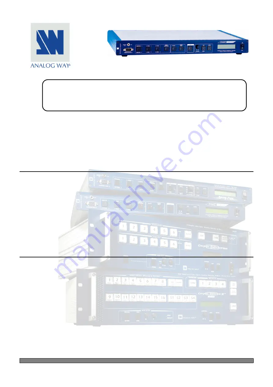
SMART CUT 2™

EDITION : 10/02  

.

SMART CUT 2

™ 

(S-CUT 2)

User’s Manual

Manuel Utilisateur

TABLE OF CONTENTS                                                                                                                               

SAFETY INSTRUCTIONS ...........................................................................................................................................................2
Chapter 1 : INTRODUCTION .......................................................................................................................................................5
Chapter 2 : INSTALLATION ........................................................................................................................................................6
Chapter 3 : TECHNICAL DESCRIPTION....................................................................................................................................7
Chapter 4 : STARTING .................................................................................................................................................................8
Chapter 5 : OPERATING MODE................................................................................................................................................12
Chapter 6 : LCD SCREEN DESCRIPTION ................................................................................................................................15
Chapter 7 : LCD FUNCTIONS DESCRIPTION .........................................................................................................................17
Chapter 8 : TECHNICAL SPECIFICATIONS ............................................................................................................................21
Chapter 9 : CONTROL SOFTWARE..........................................................................................................................................23
Chapter 10 : RS-232 PROGRAMMER'S GUIDE .......................................................................................................................28
WARRANTY...............................................................................................................................................................................75

TABLE DES MATIÈRES                                                                                                                              

INSTRUCTIONS DE SÉCURITÉ.................................................................................................................................................3
Chapitre 1 : INTRODUCTION....................................................................................................................................................40
Chapitre 2 : MONTAGE ..............................................................................................................................................................41
Chapitre 3 : DESCRIPTION TECHNIQUE ................................................................................................................................42
Chapitre 4 : MISE EN SERVICE.................................................................................................................................................43
Chapitre 5 : MODE OPÉRATOIRE.............................................................................................................................................47
Chapitre 6 : DESCRIPTION DE L'ÉCRAN LCD .......................................................................................................................50
Chapitre 7 : DESCRIPTION DES FONCTIONS DE L'ÉCRAN LCD........................................................................................52
Chapitre 8 : SPÉCIFICATIONS TECHNIQUES ........................................................................................................................56
Chapitre 9 : UTILISATION DU LOGICIEL ...............................................................................................................................58
Chapitre 10 : GUIDE DE PROGRAMMATION RS-232............................................................................................................63
GARANTIE .................................................................................................................................................................................75

Содержание S-CUT2

Страница 1: ...Chapter 8 TECHNICAL SPECIFICATIONS 21 Chapter 9 CONTROL SOFTWARE 23 Chapter 10 RS 232 PROGRAMMER S GUIDE 28 WARRANTY 75 TABLE DES MATI RES INSTRUCTIONS DE S CURIT 3 Chapitre 1 INTRODUCTION 40 Chapitre...

Страница 2: ...d from wall outlet In both cases please follow these instructions The power cord of the device should be unplugged from the outlet when left unused for several days To unplug the device do not pull on...

Страница 3: ...struer ses ouvertures Si un liquide ou un objet p n tre l int rieur de l appareil d branchez imm diatement l appareil et faites le contr ler par un personnel qualifi avant de le remettre en service IS...

Страница 4: ...e lea cuidadosamente todas las consignas de seguridad y de funcionamiento del aparato antes de usarlo Conserve las instrucciones de seguridad y de funcionamiento para que pueda consultarlas posteriorm...

Страница 5: ...tment for your display resolution The SMART CUT 2 is also a state of the art improved SCALER LINE MULTIPLIER which significantly increases the resolution and brightness of the TV image The new High qu...

Страница 6: ...tall the SMART CUT 2 into a 19 rack c Screw the supplied 19 brackets to the sides of the SMART CUT 2 d Attach the SMART CUT 2 to the rack by using 4 screws in the front panel holes screws not included...

Страница 7: ...T 1 COMPUTER 1 PC MAC WORKSTATION input on HD15 female connector AUDIO 1 IN L R COMPUTER 1 audio stereo input on 3 5 JACK connector VIDEO INPUTS C V 1 Composite video 1 input on BNC connector C V 2 Co...

Страница 8: ...uts f Connect your main computer source to the COMPUTER INPUT 1 and your second computer source to COMPUTER INPUT 2 front panel g Connect all of your audio sources to the corresponding AUDIO INPUTS h...

Страница 9: ...ble and is connected to the video equipment with an RCA or BNC connector CONNECTION 4 3 S VIDEO INPUTS The S VIDEO Super Video signal also called Y C HI 8 or S VHS is available on most DVD players and...

Страница 10: ...T VIDEO SIGNAL Y R Y B Y The Component Video signal also called YUV Y R Y B Y or BETACAM is widely used in broadcasting and is available on high quality DVD players The COMPONENT signal is transmitted...

Страница 11: ...ector and or a 5 pins MCO connector 3 5 mm jack connector The COMPUTER 1 COMPUTER 2 C VIDEO 1 and S VIDEO 1 inputs are equipped with this audio connector This connector allows to connect only UNBALANC...

Страница 12: ...tching between all the inputs will be operate with a black transition 5 1 THE SEAMLESS MODE SETTINGS c We recommend to reset the SMART CUT 2 to all of its default values with the LCD menu 5 6 before p...

Страница 13: ...video switching If not AUTO then you can lock the audio output on one video or computer audio input LCD menu 4 3 e Adjust for each audio input the audio level LCD menu 4 2 5 2 THE SCALER MODE NOT SEA...

Страница 14: ...AMLESS MODE see chapter 5 1 5 4 SYNCHRONIZATION MODE TABLE MODES THE SEAMLESS MODE THE SCALER MODE THE SCALER FOLLOW MODE APPLICATIONS Video and Computer Presentation Video presentation without comput...

Страница 15: ...the STATUS MODE press several times return without safeguarding the item ENTER button From the STATUS MODE press this button to return to the last consulted menu From the CONTROL MODE press this butt...

Страница 16: ...control menu 11 image process 6 aspect ratio 7 brightness 8 contrast 9 color 6 default value no yes 5 version 4 extend switch English all lock 3 black delay short long 3 image menu 1 H position 4 V s...

Страница 17: ...he inputs preceded by EXTEND Example EXTEND CV2 are the inputs directly connected to the SMART CUT 2 1 2 video status ENTER Indicates the status of the selected video input S VIDEO 1 Selected input NT...

Страница 18: ...Scaler mode not seamless then the LCD Menu displays a list of output formats 2 3 output format ENTER If reference sync COMPUTER 1 COMPUTER 2 COMPUTER 3 or EXTEND PC 2 the LCD window displays the refe...

Страница 19: ...nderscan Output image is full screen overscan Output image is 10 bigger than in Underscan mode 3 6 aspect ratio ENTER Select an Aspect Ratio with ENTER 4 3 4 3 Aspect Ratio 14 9 14 9 Aspect Ratio 16 9...

Страница 20: ...Delay allows to avoid any unwanted visual effects drop out or glitch on your display device short 1 second delay long 3 second delay 5 4 extend switch ENTER Select this function if you use a SMART SW...

Страница 21: ...c 0 7 V Luma C 0 3 Vp p Chroma Burst Impedance 75 Ohms COMPOSITE VIDEO BNC connector PAL SECAM 15 625 kHz 50 Hz 625L NTSC 3 58MHz 4 43 MHz 15 735 kHz 60 Hz 525L Levels 1 Vp p 0 3 V Sync 0 7 V Luma Imp...

Страница 22: ...t format is one of the formats available in the LCD menu 2 2 8 5 AUDIO OUTPUT 2 stereo outputs Balanced and Unbalanced Vo 4 dBm Max Zo 600 balanced Zo 300 unbalanced G 0 dB nominal with Master volume...

Страница 23: ...ight cable DB 9 Female DB 9 Male NOTE The Remote Keypad RK20 is not compatible when the SMART CUT 2 is used with the SMV415 If you use the SMART CUT 2 with the SMART SWITCH VIDEO and with the SMART SW...

Страница 24: ...LLATION c Turn your computer ON and wait for WINDOWS to completely start d Insert the disk into the floppy drive e In the WINDOWS START menu click on RUN f Choose the disk drive and click on setup exe...

Страница 25: ...ols menu The SMART CUT 2 is now connected to the computer make a Reset to default value Controls menu if necessary d In the Input menu select the video type for the RGB YUV input and select the video...

Страница 26: ...ect the output Sync type Sync and the Reference sync If Reference Sync no computer select the output format Format and the Output frame rate f In the Image menu make the adjustments for all of your vi...

Страница 27: ...io source Source and the Level of each audio inputs NOTE Select Automatic for audio follow switching h When a SMART SWITCH VIDEO is connected to the SMART CUT 2 select Extend Switch in the Controls me...

Страница 28: ...this command If the command cannot be executed value out of range no signal on the selected input the SMART CUT 2 will just sends back the current status of the corresponding parameters If the comman...

Страница 29: ...TS 0 3 g IRGBX1 READS VIDEO TYPE OF THE RGB YUV INPUTS h ISTDX INPUT STANDARD 0 4 1h ISTDX1 SELECTS NTSC STANDARD OUTPUT COMMANDS u SSYNC REFERENCE SYNC 0 25 u SSYNC1 READS THE REFERENCE SYNC O OFMT O...

Страница 30: ...TED INPUT DISPLAYED 0 25 I ICHAN1 SELECTED INPUT IS COMPUTER 1 INPUT MISCELLANEOUS COMMANDS Y CMD MISCELLANEOUS CONTROL 0 4095 1Y CMD1 CUT ACTION DEV DEVICE TYPE 0 65535 DEV9 READ DEVICE TYPE 9 SMART...

Страница 31: ...ES11 12 C VIDEO 5 IPRES12 13 C VIDEO 6 IPRES13 S CUT 2 14 S VIDEO 1 IPRES14 15 S VIDEO 2 IPRES15 SMV415 16 S VIDEO 3 IPRES16 17 S VIDEO 4 IPRES17 18 S VIDEO 5 IPRES18 19 S VIDEO 6 IPRES19 20 RGB YUV 1...

Страница 32: ...VIDEO 5 PCHAN12 13 C VIDEO 6 PCHAN13 S CUT 2 14 S VIDEO 1 PCHAN14 15 S VIDEO 2 PCHAN15 SMV415 16 S VIDEO 3 PCHAN16 17 S VIDEO 4 PCHAN17 18 S VIDEO 5 PCHAN18 19 S VIDEO 6 PCHAN19 20 RGB YUV 1 PCHAN20...

Страница 33: ...E APPLICATION 0 VGA 640 x 480 at 60Hz OFMT0 1 PLASMA 42 852 x 480 at 60Hz OFMT1 2 SVGA 800 x 600 at 60Hz OFMT2 3 MAC 640 x 480 at 66Hz OFMT3 4 XGA 1024 x 768 at 60Hz OFMT4 5 PLASMA 50 1280 x 768 at 56...

Страница 34: ...HARP1 2 SHARPNESS 2 SHARP2 3 SHARPNESS 3 SHARP3 ALL 4 GAMMA 1 SHARP4 5 GAMMA 2 SHARP5 6 SHARPNESS 1 GAMMA 1 SHARP6 7 SHARPNESS 2 GAMMA 1 SHARP7 b command is used to select the video input s aspect rat...

Страница 35: ...ACHAN18 19 S VIDEO 6 ACHAN19 20 RGB YUV 1 ACHAN20 21 RGB YUV 2 ACHAN21 22 RGB YUV 3 ACHAN22 23 COMPUTER 1 ACHAN23 24 COMPUTER 2 ACHAN24 25 COMPUTER 3 ACHAN25 g STATUS COMMANDS READ ONLY This control f...

Страница 36: ...are used as ref sync 0 Computer format out of range for reference sync 1 Computer format in range can be used as reference sync c command is used to know the computer number which status is displayed...

Страница 37: ...PLICATION DECIMAL VALUE STATUS OF VIDEO RESPONSE APPLICATION 0 NO VIDEO SELECTED VCHAN0 3 C VIDEO 1 VCHAN3 4 C VIDEO 2 VCHAN4 S CUT 2 5 S VIDEO 1 VCHAN5 ALONE 6 S VIDEO 2 VCHAN6 7 RGB YUV VCHAN7 SMART...

Страница 38: ...ration of the Black Delay during a switch in Fast Cut mode 0 Short time action 1 Long time action 0 Extend switch No action 1 Extend switch Yes action NOTE To modify an adjustment you should first rea...

Страница 39: ...1 I 49 73 i 69 105 2A 42 J 4A 74 j 6A 106 2B 43 K 4B 75 k 6B 107 2C 44 L 4C 76 l 6C 108 2D 45 M 4D 77 m 6D 109 2E 46 N 4E 78 n 6E 110 2 F 47 O 4 F 79 o 6 F 111 0 30 48 P 50 80 p 70 112 1 31 49 Q 51 81...

Страница 40: ...e informatique s lectionn e Ceci permet un seul r glage de votre vid o projecteur Le SMART CUT 2 est galement un MULTIPLICATEUR DE LIGNES HAUTE TECHNOLOGIE qui am liore nettement la r solution et la l...

Страница 41: ...19 merci de suivre les instructions ci dessous c Fixez les querres sur les c t s du SMART CUT 2 d Fixez la face avant du SMART CUT 2 votre la baie avec 4 vis les vis ne sont pas fournies IMPORTANT Les...

Страница 42: ...l de contr le COMPUTER INPUT 1 Entr e informatique n 1 PC MAC station de travail sur connecteur HD15 F AUDIO 1 IN L R Entr e audio st r o de l entr e informatique n 1 COMPUTER 1 sur jack 3 5 mm VIDEO...

Страница 43: ...accordez votre ordinateur principal l entr e COMPUTER INPUT 1 et votre second ordinateur l entr e COMPUTER INPUT 2 face avant g Raccordez toutes vos sources audio aux entr es audio correspondantes AUD...

Страница 44: ...transmit par un simple c ble coaxial et se raccorde aux appareils vid o par un connecteur RCA ou BNC RACCORDEMENT 4 3 ENTR ES S VIDEO Le signal S VIDEO Super Vid o aussi appel Y C HI 8 ou S VHS est di...

Страница 45: ...B Y Les signaux vid o Composantes aussi appel s COMPONENT YUV Y R Y B Y ou BETACAM sont largement utilis s dans le milieu broadcast mais sont aussi disponibles sur certain lecteur de DVD Les signaux...

Страница 46: ...mm et ou un connecteur MCO 5 points Connecteur jack 3 5 mm Les entr es COMPUTER 1 COMPUTER 2 C VIDEO 1 et S VIDEO 1 sont quip es de ce connecteur audio Ce connecteur permet de raccorder uniquement les...

Страница 47: ...AMLESS R GLAGES c Avant chaque nouvelle application nous conseillons de remettre tous les r glages par d fauts du SMART CUT 2 avec la fonction DEFAUT VALUE menu 5 6 de l cran LCD d S lectionnez le typ...

Страница 48: ...mmutations Sinon s lectionnez l entr e AUDIO qui doit tre diffus e en permanence e quilibrez le niveau des diff rentes sources audio avec la fonction audio level menu 4 2 de l cran LCD 5 2 LE MODE SCA...

Страница 49: ...ODE SEAMLESS voir chapitre 5 1 R GLAGES DE L AUDIO Identique au MODE SEAMLESS voir chapitre 5 1 5 4 TABLE DES MODES DE SYNCHRONISATION MODES MODE SEAMLESS MODE SCALER MODE SCALER FOLLOW APPLICATIONS P...

Страница 50: ...u MODE TAT appuyez plusieurs fois revenir sans valider votre s lection ENTER A partir du MODE TAT permet de revenir au dernier menu consult A partir du MODE R GLAGE permet de valider la s lection affi...

Страница 51: ...tus 4 output rate 2 output menu 3 RGB YUV in 1 output sync 3 output format 4 comput status 3 image menu 1 H position 4 V size 12 Preset 3 H size 2 V position 5 u overscan 10 hue English all lock 3 bla...

Страница 52: ...es les entr es C VIDEO S VIDEO Les entr es pr c d es par la lettre EXTEND Exemple EXTEND CV2 sont les entr es directement raccord es au SMART CUT 2 1 2 video status ENTER Indique l tat de l entr e vid...

Страница 53: ...D PC 2 NO COMPUT Mode Scaler non Seamless l cran LCD affiche alors une liste des formats de sortie 2 3 output format ENTER Si reference sync COMPUTER 1 COMPUTER 2 COMPUTER 3 ou EXTEND PC 2 l cran LCD...

Страница 54: ...c ENTER underscan L image de sortie est pleine cran overscan L image de sortie est 10 plus grande qu en mode Underscan 3 6 aspect ratio ENTER S lectionnez un format avec ENTER 4 3 Image au format 4 3...

Страница 55: ...s d une commutation non seamless La dur e du d lai permet de masquer les d fauts d images produits par votre afficheur short D lais de 1 seconde long D lais de 3 secondes 5 4 extend switch ENTER S lec...

Страница 56: ...V Synchro C 0 3 Vc c Burst Chroma Imp dance 75 Ohms VIDEO COMPOSITE connecteur BNC PAL SECAM 15 625 kHz 50 Hz 625L NTSC 3 58 MHz 4 43 MHz 15 735 kHz 60 Hz 525L Niveaux 1 Vc c 0 7 V Luma 0 3 V Synchro...

Страница 57: ...n mode scaler le format de sortie et l un de ceux disponible dans le menu n 2 2 de l cran LCD 8 5 SORTIES AUDIO OUTPUT 2 sorties st r o Sym triques et Asym triques Vo 4 dBm Max Zo 600 sym trique Zo 30...

Страница 58: ...CUT 2 avec un c ble droit DB 9 Femelle DB 9 M le NOTE Le Remote Keypad RK20 n est pas compatible lorsque le SMART CUT 2 est utilis avec le SMV415 Si vous utilisez le SMART CUT 2 avec le SMART SWITCH...

Страница 59: ...NSTALLATION c Allumez votre ordinateur et attendez que WINDOWS d marre compl tement d Ins rer la disquette 3 5 dans le lecteur de disquette de votre ordinateur e Dans le menu D marrer de WINDOWS cliqu...

Страница 60: ...ols Le SMART CUT 2 est maintenant connect l ordinateur effectuez un Reset to default values menu Controls si n cessaire d Dans le menu Input s lectionnez le type de vid o pour l entr e RGB YUV et s le...

Страница 61: ...t sync et le mode de synchronisation Reference sync Si Reference sync no computer s lectionnez le format de sortie Format et le mode de synchronisation de la trame Output frame rate f Dans le menu Ima...

Страница 62: ...urce audio Source et le niveau pour chaque entr e audio Level NOTE S lectionnez Automatic pour une commutation audio follow h Lorsqu un SMART SWITCH VIDEO est raccord au SMART CUT 2 s lectionnez Exten...

Страница 63: ...a commande n est pas reconnue valeur en dehors de la plage pas de signal sur l entr e s lectionn e l appareil renvoie uniquement l tat de tous les param tres standard vid o r glage d image Si la comma...

Страница 64: ...NTR E RGB YUV h ISTDX STANDARD D ENTR E 0 4 1h ISTDX1 S LECTIONNE LE STANDARD NTSC COMMANDES DE SORTIE u SSYNC SYNCHRO DE R F RENCE 0 25 u SSYNC1 DONNE LA REF DE SYNCHRO O OFMT FORMAT DE SORTIE 0 13 O...

Страница 65: ...COMPUTER 1 EST S LECTIONN E AUTRES COMMANDES Y CMD AUTRES CONTR LES 0 65535 1Y CMD1 COMMANDE DU CUT DEV TYPE DE PRODUIT 0 65535 DEV5 DONNE LE TYPE DU PRODUIT 9 S CUT 2 K K_ VERSION DU COMPOSANT K 0 6...

Страница 66: ...RES11 12 C VIDEO 5 IPRES12 13 C VIDEO 6 IPRES13 S CUT 2 14 S VIDEO 1 IPRES14 15 S VIDEO 2 IPRES15 SMV415 16 S VIDEO 3 IPRES16 17 S VIDEO 4 IPRES17 18 S VIDEO 5 IPRES18 19 S VIDEO 6 IPRES19 20 RGB YUV...

Страница 67: ...5 PCHAN12 13 C VIDEO 6 PCHAN13 S CUT 2 14 S VIDEO 1 PCHAN14 15 S VIDEO 2 PCHAN15 SMV415 16 S VIDEO 3 PCHAN16 17 S VIDEO 4 PCHAN17 18 S VIDEO 5 PCHAN18 19 S VIDEO 6 PCHAN19 20 RGB YUV 1 PCHAN20 21 RGB...

Страница 68: ...TIE R PONSE APPLICATION 0 VGA 640 x 480 60Hz OFMT0 1 PLASMA 42 852 x 480 60Hz OFMT1 2 SVGA 800 x 600 60Hz OFMT2 3 MAC 640 x 480 66Hz OFMT3 4 XGA 1024 x 768 60Hz OFMT4 TOUTES 5 PLASMA 50 1280 x 768 56H...

Страница 69: ...SHARPNESS 2 SHARP2 3 SHARPNESS 3 SHARP3 TOUTES 4 GAMMA 1 SHARP4 5 GAMMA 2 SHARP5 6 SHARPNESS 1 GAMMA 1 SHARP6 7 SHARPNESS 2 GAMMA 1 SHARP7 La commande b est utilis e pour s lectionner un aspect ratio...

Страница 70: ...ACHAN21 22 RGB YUV 3 ACHAN22 23 COMPUTER 1 ACHAN23 24 COMPUTER 2 ACHAN24 25 COMPUTER 3 ACHAN25 g COMMANDES D ETATS LECTURE SEULE Cet ensemble de commandes peut uniquement tre lu Ces commandes ne peuv...

Страница 71: ...tr e informatique dont l tat est affich APPLICATION SMART CUT 2 SEUL VALEUR DECIMALE S LECTION R PONSE APPLICATION 0 NO COMPUTER CCHAN0 S CUT 2 1 COMPUTER 1 CCHAN1 SEUL 2 COMPUTER 2 CCHAN2 APPLICATION...

Страница 72: ...IMALE TAT DE LA VID O R PONSE APPLICATION 0 PAS DE VIDEO S LECTIONN E VCHAN0 4 EXTEND C VIDEO 2 VCHAN4 6 EXTEND S VIDEO 2 VCHAN6 8 C VIDEO 1 VCHAN8 9 C VIDEO 2 VCHAN9 10 C VIDEO 3 VCHAN10 11 C VIDEO 4...

Страница 73: ...t 1 Long 0 Extend Switch Non 1 Extend Switch Oui NOTE Pour modifier un r glage il faut d abord lire l tat de la commande puis modifier la valeur du bit correspondant au r glage effectuer sans modifier...

Страница 74: ...9 41 I 49 73 i 69 105 2A 42 J 4A 74 j 6A 106 2B 43 K 4B 75 k 6B 107 2C 44 L 4C 76 l 6C 108 2D 45 M 4D 77 m 6D 109 2E 46 N 4E 78 n 6E 110 2 F 47 O 4 F 79 o 6 F 111 0 30 48 P 50 80 p 70 112 1 31 49 Q 51...

Страница 75: ...escription of the problem and then call your authorized dealer GARANTIE Analog Way garantie le produit contre les d fauts mat riels et vices de fabrication pour une p riode de 3 ans partir de la date...

Отзывы: