


ADXL180
Rev. 0 | Page 30 of 56
TRANSMIT DELIMITER CODE
PHASE 1
PHASE 3
PHASE 2
MODE 2
63
Mode 2
Device Data
When Mode 2 is selected, the device data that is transmitted
consists of the UREG byte, four configuration register bytes (see
Figure 24), and the 4-byte serial number. The data is transmitted
one bit per message. Each message represents either a Logic 0 or
a Logic 1. The code, 0x7A (+122d), represents a Logic 0 and the
code, 0x79 (+121d), represents a Logic 1 in 8-bit data mode. See
Table 30 for both 8-bit and 10-bit data coding.
The delimiter code
depends on the range setting in the configuration registers. The
delimiter byte used for each range setting is listed in Table 31.
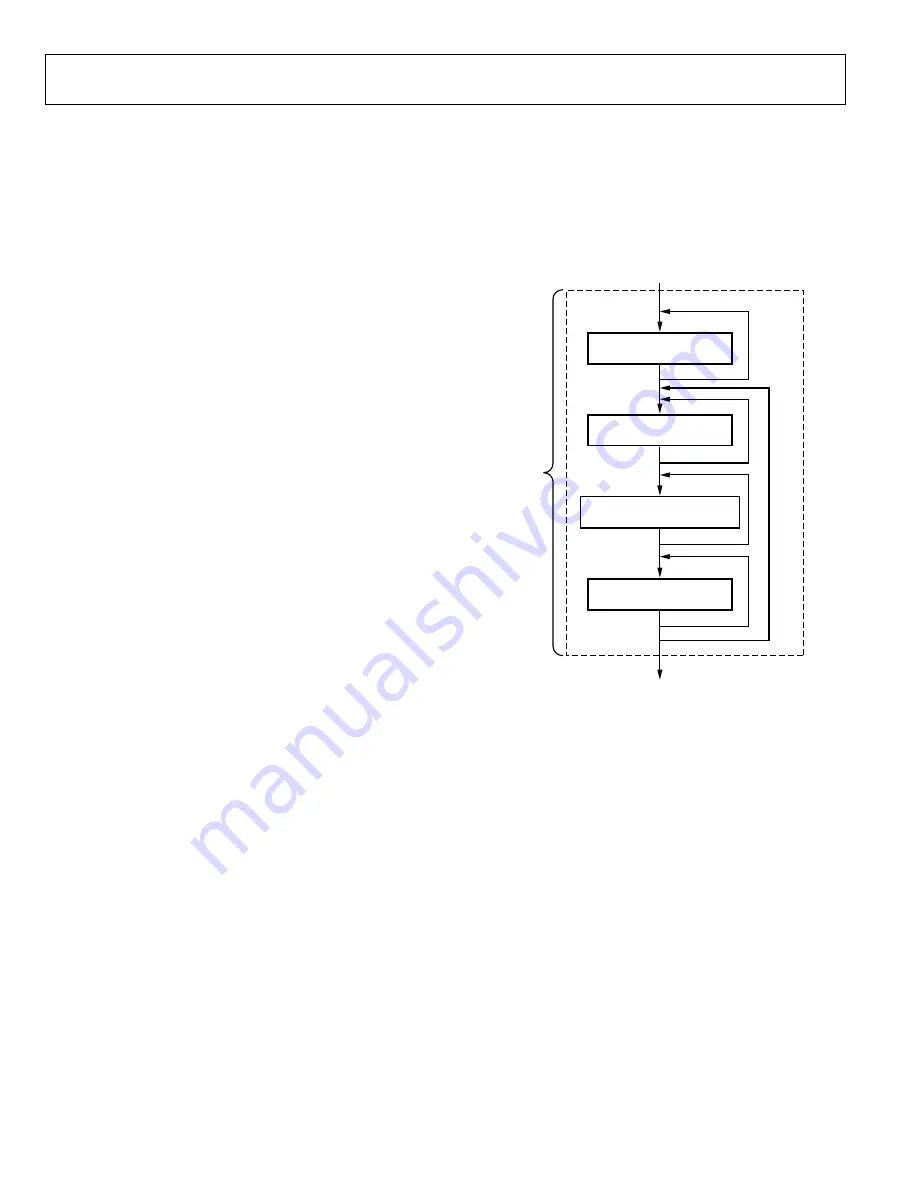
The data is transmitted in the following sequence and as shown
in Figure 23. The total number of messages transmitted during
Mode 2 Phase 2 is 480.
1.
Transmit delimiter code 64 times.
2.
Transmit 32 messages of serial number data (32 bits of
information, one bit per message).
3.
Transmit 12 messages of user bits (12 bits of information,
one bit per message). See Table 32.
4.
Transmit delimiter code eight times.
5.
Repeat Step 2 through Step 4 seven times.
User Bits and User Register (UREG)
The user bits (U11 to U0) information transmitted during
Phase 2 Mode 2 maps into the user and configuration register
data stored in the OTP memory of the ADXL180. This includes
the 8-bits in the UREG. The mapping is shown in Table 32. See
the Configuration Specification section for information about
the definition and function of the user and configuration
registers data bits.
10-Bit Data and Mode 2
During Phase 2 when both Mode 2 and the 10-bit data mode
are selected, all device data messages are transmitted with two
zero-value LSBs appended (that is, left-justified data). Note that,
when Mode 2 is selected with the state vector enabled and the
auto-zero is not enabled, the full range sensor data coding is
used (see the Data Frame Transmission Format section).
Therefore, the positive and negative full-scale ends of the sensor
data range overlap with the device data and status/error codes.
The state vector distinguishes between the types of transmitted
data. The state vector identifies the device data (state vector =
001b) and the status/error codes (state vector = 110b). Normal
operation sensor data has a state vector of 000b. See Table 19
and Table 16.
TRANSMIT SN DATA BIT CODE
480 ×
t
P
TRANSMIT USER DATA BIT CODE
TRANSMIT DELIMITER CODE
31
11
7
7
07
54
4-
0
44
Figure 23. Phase 2 Mode 2 State Machine


