background image

UDM-RX02N Wiring and Connections

45

UDM-0808-SIG, UDM-RX02N and UDM-ABB-8-SIG Operation /Reference Guide

Using the UDM-RC05 for Video Compensation

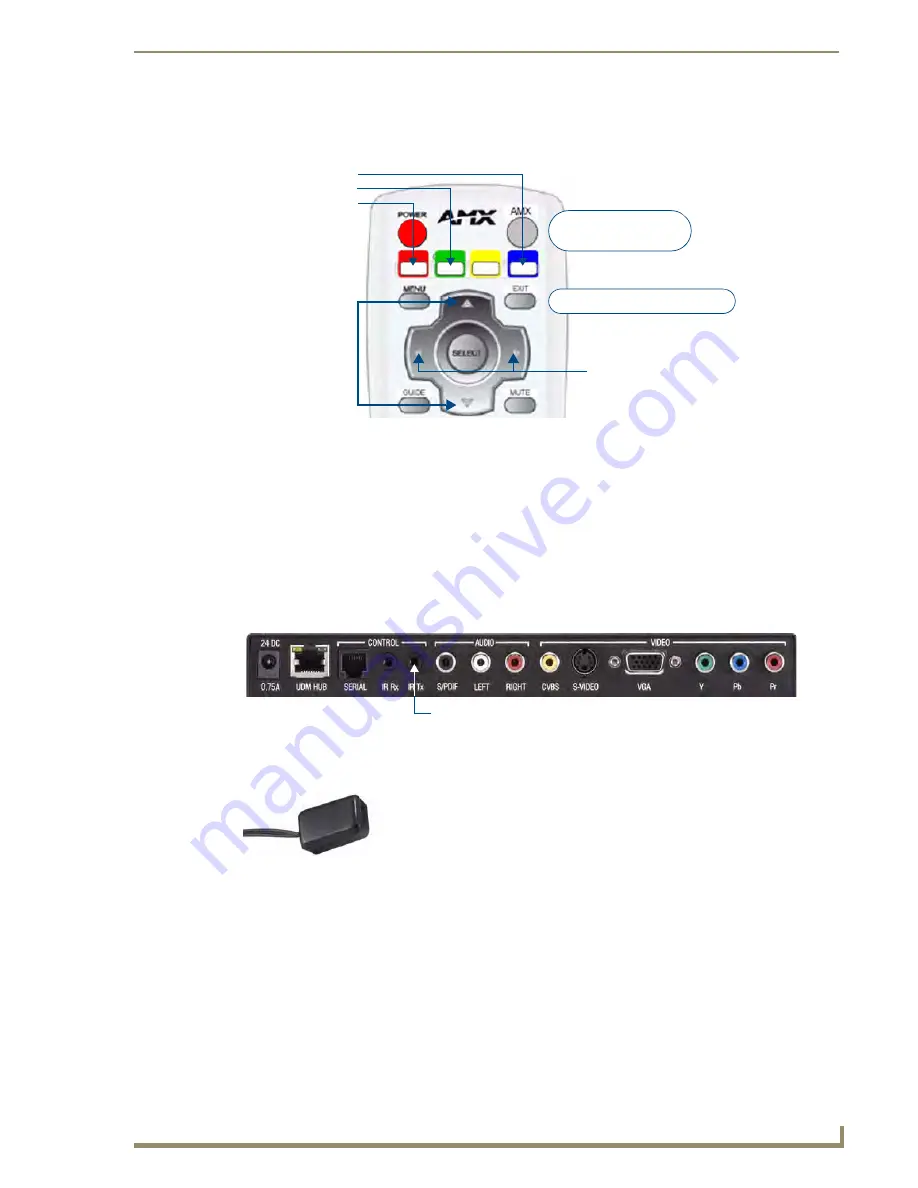
FIG. 41 indicates the buttons on the UDM-RC05 IR Remote Control that can be used for video compensation 
n the UDM-RX02N: 



Enter setup mode - press AMX, then MENU 



Exit setup mode - EXIT 



Red skew increase - RED 



Green skew increase - GREEN 



Blue skew increase - BLUE 



Gain (brightness) - LEFT and RIGHT



Sharpness - UP and DOWN 

IR Tx (IR Transmitter) Port

The IR Tx IR Transmitter port supports wired control of connected IR devices (FIG. 39). 

To issue IR commands to a display device, an IR01 External IR Emitter Module (FG-IR01, not included) is 
required. 

To connect an IR Emitter:

1.

Connect an IR01 IR Emitter cable (FG-IR01) to the IR Tx port on the UDM-RX02N.

2.

Run the other end of the IRTX cable to the display device and locate the IR window.

3.

Attach the IR Emitter bud over the device’s IR sensor by removing the cover of the reverse side of the 
Emitter and sticking it directly over the IR window.

FIG. 41  

UDM-RC05 IR Remote Control - Video Compensation buttons

FIG. 42  

UDM-RX02N - IR Tx Port

FIG. 43  

IR01 IR Emitter

Red skew increase

Green skew increase

Blue skew increase

Gain (Brightness)

Press 

AMX

 then 

MENU

to enter Setup mode

Press 

EXIT 

to exit Setup mode

Sharpness

IR Tx (IR Transmitter) Port

IR01 IR Emitter (FGIR01)

Содержание UDM-RX02N

Страница 1: ...ference Guide Universal Distribution Matrix UDM 0808 SIG 8x8 Signature Series Multi Format Distribution Hub UDM RX02N Multi Format Receiver UDM ABB 8 SIG Signature Series Audio Breakout Box Last Revised 11 15 2010 ...

Страница 2: ...rked on the outside of each box The RMA is valid for a 30 day period After the 30 day period the RMA will be cancelled Any shipments received not consistent with the RMA or after the RMA is cancelled will be refused AMX is not responsible for products returned without a valid RMA number AMX is not liable for any damages caused by its products or for the failure of its products to perform This incl...

Страница 3: ...istribution Hub 1 Overview 1 Features 1 Common Application 1 Compatibility 1 Product Specifications 2 Configuration Options 3 Rack Mounting the UDM 0808 SIG 3 Ventilation 4 UDM 0808 SIG Wiring and Connections 5 Overview 5 UDM 0808 SIG Front Panel Components 5 Power Status bar 5 Status LEDs 5 UDM 0808 SIG Rear Panel Components 6 Connecting UDM RX02N Receivers to the UDM 0808 SIG 6 UDM Output Ports ...

Страница 4: ...0 IEC Power Connector 11 Powering the UDM 0808 SIG Hub On 11 Powering the UDM 0808 SIG Hub Off 11 UDM 0808 SIG NetLinx Programming 13 Overview 13 Device Numbering 13 LEVELs 14 SEND_COMMANDs 15 FWVERSIOND 15 TEMP 15 AI 15 A 16 CI 16 CL 17 C 17 MMOFF 18 MMON 18 MM 18 RESET 18 RESETFACTORY 19 RPUOFF 19 RPUON 19 RPU 19 SAI 20 SAI 20 SFI 20 SFI 21 SVI 21 SVI 21 VI 22 V 22 UDM 0808 SIG WebConsole 23 Ove...

Страница 5: ... Configuration Manager With Security Enabled 28 IP Settings 29 Port Settings 30 Clock Manager 30 Clock Manager Mode Manager 31 Clock Manager Daylight Savings 32 Clock Manager NIST Servers 33 UDM 0808 SIG Firmware Upgrades 35 Overview 35 Before You Start 35 Sending a Firmware KIT File To the UDM 0808 SIG 35 Firmware Readme TXT 37 Additional Documentation 37 UDM RX02N Multi Format Receiver 39 Overvi...

Страница 6: ...6 CVBS Composite Video Output Port 46 S VIDEO Video Output Port 46 VGA Video Output Port 47 Component Y Pb Pr Video Output Port 47 Video Compensation 48 UDM RX02N NetLinx Programming 49 Overview 49 Device Numbering 49 CHANNELs 50 LEVELs 50 SEND_COMMANDs 50 RP 50 RP 51 SB 51 SB 51 SD 51 SKB 51 SKG 51 IR SEND_COMMANDs 52 IR CHANNELs 52 IR SEND_COMMANDs 52 CAROFF 52 CARON 52 SKR 52 SK 52 SS 52 SS 52 ...

Страница 7: ...brary IRL File To the UDM RX02N 63 Additional Documentation 65 UDM RC05 Multi Format IR Remote Control 67 Overview 67 IR Codes UDM RC05 Pushbuttons 67 Using the UDM RC05 for Video Compensation 69 UDM ABB 8 SIG Audio Breakout Box 71 Overview 71 Common Application 71 Features 71 Compatibility 71 Product Specifications 72 Connecting the UDM ABB 8 SIG to an UDM 0808 SIG 72 Connecting Audio Outputs 73 ...

Страница 8: ...08 SIG Hub For Cascading 79 Using the UDM ABB 8 SIG Audio Breakout Box 79 Cascading Two Hubs Cable Connections 81 Cascading up to Four Hubs Cable Connections 81 Configuring the Source Hub 82 MMON Send Command 82 Configuring the Hub as a Target Hub 83 MMOFF Send Command 83 Specifying Cascaded Ports 83 SVI Send Command 83 Cascading Hubs Code Examples 84 Appendix 85 Ascii Hex Conversion 85 ...

Страница 9: ... risk of injury There are NO user serviceable parts within the UDM Hub Rating Label The rating label FIG 2 containing important safety information is found on the underside of the UDM Hub Symbols used on this label are explained below FIG 1 Voltage symbol FIG 2 Rating Label The UDM Hub is powered from a suitable 24 VDC supply FCC Federal Communications Commission Standards TESTED TO COMPLY FOR HOM...

Страница 10: ...le and expel warm air through the grilles on the left side ventilation grilles Humidity DO NOT install or operate the UDM Hub in an area in which the ambient relative humidity exceeds 85 or an area that is prone to condensation Water Liquids DO NOT install or operate the UDM Hub near water or in a location which may be prone to water seepage dripping or splashing DO NOT place objects containing li...

Страница 11: ... via the HD15 Input connector on the rear of the UDM Adapters are used to bring the different types of video source into the UDM Each UDM has an Ethernet network port to provide connectivity to a central management system A Serial connection is also provided for CLI diagnostic purposes Features 8 multi format inputs x 8 outputs Native NetLinx End device control IR Serial Digital and Analog audio s...

Страница 12: ...luded Composite requires an UDM HD15RCA3 Breakout Cable FG HD15RCA3 not included Max Video Input 8 x RGBHV or 8 x S Video or 8 x component or 24 composite inputs Audio Inputs Analog Audio In RCA female analog audio connectors white Left red Right SPDIF Audio In RCA female digital audio connector black NETWORK Port RJ45 Ethernet port provides 100 BaseT network connectivity SERIAL Port RJ12 port all...

Страница 13: ...3 5 x 19 x 12 1 2 889 mm x 440 mm x 320 mm 2 RU Weight 13 6 lbs 6 16 kg Certifications CE FCC part 15 Class A Included Accessories IEC power cord 19 mounting brackets UDM RC05 Multi Format IR Remote Control FG1402 70 IR03 External Infrared Receiver Module FG IR03 Note No A V interface cables supplied Other AMX Equipment HD15 to S Video Cable FG UDM SVID01 HD15 to 3x RCA Breakout Cable FG HD15RCA3 ...

Страница 14: ...entilation ALWAYS ensure that the rack enclosure is adequately ventilated Sufficient airflow must be achieved by convection or forced air cooling to satisfy the ventilation requirements of all the items of equipment installed within the rack FIG 3 Screw the Hub into the rack using the fixing holes Mounting holes 2 per side DO NOT stand other units directly on top of the Hub when it is rack mounted...

Страница 15: ...r Status bar The blue light bar on front panel indicates that the unit is powered Status LEDs The eight blue LEDs on the front panel light to indicate which of the eight outputs are currently routing video to a connected UDM RX02N Receiver FIG 4 UDM 0808 SIG System Diagram FIG 5 UDM 0808 SIG Front Panel Components TV LCD Plasma Video Projector Screen 1500VG Touch Panel NI 3101 SIG NetLinx Master V...

Страница 16: ...nformation for the UDM port An incorrectly terminated cable will result in the following scenarios FIG 6 UDM 0808 SIG Rear Panel Components A V Transmission Over UTP UDM RJ45 Pin 568A Termination A V Signals 568B Termination Color Pair RGB YPbPr CVBS S Video Color Pair 1 3 Red Y CVBS S1 Y 2 2 3 Red Y CVBS S1 Y 2 3 2 Blue Pr CVBS S3 C 3 4 1 Green Pb CVBS S2 1 5 1 Green Pb CVBS S2 1 6 2 Blue Pr CVBS...

Страница 17: ... the appropriate VIDEO IN connector A H on the UDM 0808 SIG 3 Connect the source audio to the analog RCA audio jacks or digital SPDIF Input connector FIG 7 A V Source Input connectors A and B shown FIG 8 VIDEO IN HD15 Connector Video Input female HD15 Digital Audio Input SPDIF RCA Audio Inputs L R 1 2 3 4 5 6 7 8 9 10 11 12 13 14 15 HD15 Pinouts Input Pin 1 2 3 4 5 6 7 8 9 10 11 12 13 14 15 VGA Re...

Страница 18: ...t the maximum distances indicated above are not absolute but are recommended distances that have been tested to deliver video at the specified resolutions without significant signal degradation In particular lower resolutions 640 x 480 720 x 480 and 800 x 600 can often be delivered significantly further than what is indicated in the table Several factors affect the overall quality of the displayed...

Страница 19: ...e pinouts and signals for the Network RJ45 connector and cable By default the UDM 0808 SIG is configured for DHCP Refer to the IP Settings section on page 29 for details SERIAL RJ12 Port The SERIAL RJ12 port on the rear panel is available for diagnostic and troubleshooting purposes The Serial port on the UDM 0808 SIG is an RJ12 connector and requires a DB9 to RJ12 adapter cable FG RS01 not include...

Страница 20: ...B 8 SIG Signature Series Audio Breakout Box FG1402 60 Refer to the UDM ABB 8 SIG Audio Breakout Box section on page 71 for details Refer to the Cascading Hubs section on page 77 for details on configuring cascaded Hubs Default Serial Settings Baud Rate 115200 Data Bits 8 Parity None Stop Bits 1 Flow Control None DB9 to RJ12 Adapter Cable Pinouts DB9 connector Function Abbreviation RJ12 connector P...

Страница 21: ...oots the left most front panel LED FIG 11 will blink until the Hub is fully booted and connected to a NetLinx Master If the Hub is not configured to properly connect to a master it will continue to blink indefinitely until the configuration is changed Powering the UDM 0808 SIG Hub Off To turn the UDM 0808 SIG off flip the Power switch to it s Off 0 position As a Class 1 appliance the UDM 0808 SIG ...

Страница 22: ...UDM 0808 SIG Wiring and Connections 12 UDM 0808 SIG UDM RX02N and UDM ABB 8 SIG Operation Reference Guide ...

Страница 23: ...vice number for each UDM RX02N Receiver currently connected to the Hub is automatically designated a device number based on the device number of the Hub to which it is connected and the number of the UDM Output RJ45 port on the Hub 1 8 to which it is physically connected FIG 12 NetLinx Studio Online Tree indicating UDM 0808 SIG hubs and connected RX02N receivers UDM RX02N Receiver number auto assi...

Страница 24: ...ollowing the UDM Hub s device number assignment for up to eight UDM RX02N receivers In the device tree each UDM RX02N Receiver shows three ports FIG 13 These three ports relate directly to the three types of NetLinx commands recognized by the UDM RX02N Port 1 SEND_COMMANDS LEVELS and Button Pushes Port 2 SERIAL RS232 SEND_COMMANDS Port 3 IR SEND_COMMANDS Refer to the UDM RX02N NetLinx Programming ...

Страница 25: ... then the command will return the version number of the Hub TEMP Returns internal temperature in degrees Celsius Syntax SEND_COMMAND DEV TEMP Example SEND_COMMAND dvUDM TEMP Return value TEMP temperature AI Connect audio inputs to outputs Syntax SEND_COMMAND DEV AI I O O Variables I input number initial I may be omitted if desired 1 8 Inputs A H a value of 0 means no input disconnect O output port...

Страница 26: ...he form AO II Where O is the queried output port number I is the connected input number zero if disconnected For example A6 I3 Indicates that audio output 6 was connected to input 3 CI Connect video and audio inputs to outputs Syntax SEND_COMMAND DEV CI I O O Variables I input number 1 8 Inputs A H a value of 0 means no input disconnect O output port number 1 8 Outputs 1 8 a value of 0 or ALL mean...

Страница 27: ... to outputs 4 through 8 Example 3 SEND_COMMAND dvUDM CLAUDIOI4O1 2 6 7 8 Connects audio only on input D to outputs 1 2 6 7 and 8 Example 4 SEND_COMMAND dvUDM CLAUDIOI0O1 4 5 Disconnect audio source from outputs 1 4 5 Example 5 SEND_COMMAND dvUDM CLVIDEOI2O0 Connect video on input B to all outputs C Returns connection status for video outputs in the Hub Syntax SEND_COMMAND DEV C O Variables O outpu...

Страница 28: ... Source Hub in a chain This command configures the cascade video outputs to be correctly driven and designates this Hub to generate audio and data clocks This command takes effect the next time the Hub is rebooted via the RESET command or a power cycle Syntax SEND_COMMAND DEV MMON Example SEND_COMMAND dvUDM MMON Sets this Hub to Master Mode Note If Source or Target mode is changed then the Hub mus...

Страница 29: ...l is set to RPAMX After reboot All webserver settings are set to default RPUOFF Configures the Hub to clear all connec tions and status after a power up or reboot Syntax SEND_COMMAND DEV RPUOFF Example SEND_COMMAND dvUDM RPUOFF Configures the Hub so that connections and status are cleared after a power up or reboot RPUON Configures the Hub to restore status and connections after a power up or rebo...

Страница 30: ...s input G to accept digital audio from back panel SAI Returnsconfiguration of audio inputs Syntax SEND_COMMAND DEV SAI I Variables I input number a value of zero indicates all inputs initial I may be omitted 1 8 Inputs A H Example 1 SEND_COMMAND dvUDM SA3 Returns configuration of input C Example 2 SEND_COMMAND dvUDM SA Returns configuration of all inputs SFI Determines whether the cascade audio ou...

Страница 31: ... the local back panel connection or cascaded from an upstream Hub Syntax SEND_COMMAND DEV SVI I T T C C Variables I input number a value of zero indicates all inputs initial I may be omitted 1 8 Inputs A H 0 All inputs T type of incoming video VGA CVBS SVIDEO COMP C Cascade selector if present assume CASCADE if not assume LOCAL LOCAL CASCADE Example 1 SEND_COMMAND dvUDM SV2TVGA Sets input B to acc...

Страница 32: ...eo to output 4 Example2 SEND_COMMAND dvUDM VI3O0 Connect input C video to all outputs V Returns connection status for video outputs in the Hub Syntax SEND_COMMAND DEV V O Variables O output port number 1 8 Outputs 1 8 a value of 0 or ALL means all outputs Example 1 SEND_COMMAND dvUDM V Returns which video inputs are connected for all outputs Example 2 SEND_COMMAND dvUDM V3 4 Returns which video in...

Страница 33: ...Client You will need a zero configuration client to determine the IP address of the UDM 0808 SIG There are many zero configuration clients available However for the purposes of this document we will refer to Bonjour for Windows It is free and widely available for download If you don t already have it installed on your PC download and install Bonjour for Windows before you begin 1 With Bonjour for ...

Страница 34: ... changes to the IP Settings page and to access the other pages described in this section Admin Menu There are several configuration pages included in the Configuration Manager all of which are accessed via the Admin drop down menu FIG 16 Click on an option in this menu to access each of the configuration pages as described in the following sub sections FIG 15 Bonjour for Windows example screen UDM...

Страница 35: ...t button to send the command 5 Click the Refresh button to receive new replies notifications New replies are added to the bottom of the list Press the Clear button to clear the Replies window Sending Commands to a Connected UDM RX02N 1 Select the target receiver RX1 RX8 from the Device drop down menu 2 Check the Send as string option 3 Select the appropriate port on the RX02N to receive the comman...

Страница 36: ...he device number of the UDM 0808 SIG By default the Device Number assigned to the UDM 0808 SIG is 05600 To change the device number enter the new device number and click Accept or click Cancel to discard changes Master Connection tab Click the Master Connection tab in the Device Configuration page to view edit the Master Connection for the Hub FIG 19 Use the options on this page to view edit the C...

Страница 37: ...he page to specify security options and login information for this UDM 0808 SIG Hub The options under Mode Settings will change depending on the Connection Mode selected Connection Modes and Mode Settings Options TCP IP URL Master IP URL Master Port Number The default value is 1319 and should not be changed TCP IP Listen Master Port Number The default value is 1319 and should not be changed TCP IP...

Страница 38: ...sword are required to establish a Telnet or SSH connection default disabled Admin Security Click this checkbox to enable Admin Security With Admin Security enabled a username and password are required to modify any system configuration item default disabled Restore Factory Defaults Click to restore all security settings to their factory default all disabled Accept Click to save changes Changes on ...

Страница 39: ... Windows to detect the UDM 0808 SIG on the network See the Bonjour Zero Configuration Client section on page 23 for details Hostname Enter a Hostname for this unit enabled only if DHCP is disabled IP Address Enter an IP Address for this unit enabled only if DHCP is disabled Subnet Mask Enter a Subnet Mask for this unit enabled only if DHCP is disabled Gateway Enter a Gateway for this unit enabled ...

Страница 40: ...u FIG 24 Each of the options listed in the submenu are also accessible via options on the Clock Manager page FIG 25 FIG 23 Port Settings page HTTP Port Number Default enabled default port number 80 HTTPS Port Number Default enabled default port number 443 Telnet Port Number Default enabled default port number 23 SSH Port Number Default enabled default port number 22 FTP Port Number Default enabled...

Страница 41: ...ns to select either Network Time or StandAlone Note If using StandAlone mode the time will be valid only until the unit is rebooted Once the unit is rebooted the time will be lost and will have to be reset Note that the Daylight Savings and NIST Servers tabs are enabled only if Net work Time is selected as the mode Re Sync Period Select the desired re synch period for the clock from this drop down...

Страница 42: ...low you to specify when to start using daylight savings time Select a month and time to start from the drop down menus Select Fixed to start daylight savings at a specific Day Month and Time an additional field for Day is provided when this radio button is selected Select Occurrence to start daylight savings at a specified occurrence additional fields for Week of the Month and Day of the Week are ...

Страница 43: ...r page The options on this page allow you to select the NIST server that will be queried at each clock synchronization and allow you to add more NIST servers to the list To add a NIST server enter the NIST Server Name IP Address and Location in the fields provided To remove a NIST server from the list click the Remove button Click Accept to save your changes Note that changes on this page take eff...

Страница 44: ...UDM 0808 SIG WebConsole 34 UDM 0808 SIG UDM RX02N and UDM ABB 8 SIG Operation Reference Guide ...

Страница 45: ...owered On 5 Determine the Device Number assigned to the target UDM 0808 SIG By default the Device Number assigned to the UDM 0808 SIG is 05600 The Device Number can be viewed edited in the UDM 0808 SIG Configuration Manager Device Configuration Page see the Device Configuration tab section on page 26 for details 6 Launch NetLinx Studio and open the Online Device Tree Sending a Firmware KIT File To...

Страница 46: ...tory path is displayed in the Send To NetLinx Device dialog Location text box Assuming that the specified target directory contains one or more KIT files the KIT files in the selected directory are displayed in the Files list box with the file s last modified date and time FIG 31 FIG 29 Send To NetLinx Device dialog NetLinx Studio FIG 30 Browse For Folder dialog NetLinx Studio Browse for folder co...

Страница 47: ...ts are upgraded During the upgrade process the left most front panel LED s will blink and the device stays offline Telnet to the IP of the UDM Hub type MSG ON enter to see firmware transfer progress of each of the subcomponents Once the upgrade is complete the LED will stop blinking and the Hub will come online Firmware Readme TXT For details on any particular firmware release refer to the Readme ...

Страница 48: ...UDM 0808 SIG Firmware Upgrades 38 UDM 0808 SIG UDM RX02N and UDM ABB 8 SIG Operation Reference Guide ...

Страница 49: ...ayed in rooms throughout a residence or in classrooms conference rooms presentation rooms or other commercial applications Features Video Support for 1600 x 1200 UXGA 1920 x 1080 HDTV Component Y Pb Pr S Video CVBS PAL NTSC S PDIF Digital and analog stereo audio support IR blaster and receiver ports Compatibility The UDM RX02N is primarily intended for use with the UDM 0808 SIG Hub FG1402 01 The U...

Страница 50: ...located IR devices IR Tx 3 5mm Port 3 5mm IR Transmitter output port allows one IR controlled device such as a DVD or VCR player to be controlled via optional wired IR emitter Audio Connectors Black RCA female connector Digital audio White RCA female connector Analog audio Left Red RCA female connector Analog audio Right Video Connectors Yellow RCA female connector CVBS supports composite video S ...

Страница 51: ...er supply insert the barrel connector of the power supply into the power connector on the UDM RX02N FIG 34 To power down the UDM RX02N remove the barrel connector of the power supply from the power connector and remove the patch cable from the UDM HUB RJ45 connector FIG 33 UDM RX02N Hub and Serial Ports Serial port RJ12 IR Rx port SPDIF Digital Audio port RCA Audio Left Right CVBS port S Video por...

Страница 52: ...the power is switched on two LEDs will be visible at the UDM HUB port UDM Port LEDs 2 LEDs are visible at the UDM HUB port on the UDM RX02N when the Hub is switched on Green Audio Control Communication from UDM Hub if UTP patch cable is removed LED switches off Amber Power A V Transmission Over UTP UDM RJ45 Pin 568A Termination A V Signals 568B Termination Color Pair RGB YPbPr CVBS S Video Color P...

Страница 53: ...9 DB9 adaptor with the FG RS01 In some cases the null modem adaptor may need a link between RTS CTS at the DB9 end For example NEC LCD panels act as DTE equipment and work with standard serial cable while Fujitsu and Panasonic Plasma screens act as DCE equipment and therefore require cross connections FIG 38 describes the pinouts on the SERIAL RJ12 connector The UDM RX02N can be controlled via SEN...

Страница 54: ...a an AMX or UDM remote control then an IR03 External IR Receiver FG IR03 not included is required to receive IR commands from the remote control Likewise an IR Receiver is required to compensate video on the UDM RX02N using the UDM RC05 Endeleo remote control To connect an IR Receiver to the UDM RX02N 1 Connect the IR03 IR Receiver cable to the IR Rx port on the UDM RX02N 2 Run the cable and attac...

Страница 55: ...ssue IR commands to a display device an IR01 External IR Emitter Module FG IR01 not included is required To connect an IR Emitter 1 Connect an IR01 IR Emitter cable FG IR01 to the IR Tx port on the UDM RX02N 2 Run the other end of the IRTX cable to the display device and locate the IR window 3 Attach the IR Emitter bud over the device s IR sensor by removing the cover of the reverse side of the Em...

Страница 56: ...ect its audio to the audio connectors on the UDM RX02N S VIDEO Video Output Port FIG 47 describes the pinouts on the S VIDEO connector FIG 44 UDM RX02N AUDIO and VIDEO Output Connectors UDM RX02N Output Connectors Audio SPDIF Digital audio Left Analog audio left Right Analog audio right Video CVBS Composite Video Blanking Sync analog video S Video S Video VGA HD 15 female connector for VGA format ...

Страница 57: ...e and make a firm connection 3 If the display device has audio feeds connect its audio to the audio connectors on the UDM RX02N Component Y Pb Pr Video Output Port 1 Attach the Component cables to the Y green Pb blue and Pr red connectors on the UDM RX02N 2 Run the other end of the Component cable to the Component connectors on the display device and make sure of a firm connection 3 If the display...

Страница 58: ...de Video Compensation Video can be compensated at the UDM RX02N using two methods Via the UDM 0808 SIG using the NetLinx LEVEL Commands listed in the LEVELs section on page 50 Via the included UDM RC05 UDM Remote Control see the Using the UDM RC05 for Video Compensation section on page 69 for details ...

Страница 59: ...e UDM 0808 SIG Hub is automatically designated a device number based on the device number of the Hub to which it is connected and the number of the UDM OUTPUT port on the Hub 1 8 to which it is physically connected Therefore it important to avoid assigning device numbers that will conflict with this auto numbering scheme Reserve the eight device numbers following the UDM Hub s device number assign...

Страница 60: ...s the delay added to a video signal to compensate for different pair lengths in the cable a value of 0 applies no delay whereas a value of 31 maximum applies 62nS delay 16 Green skew controls the delay added to the green video signal 17 Blue skew controls the delay added to the blue video signal UDM RX02N SEND COMMANDs RP Sets the protocol used by the IR remote The Rx can support a number of diffe...

Страница 61: ...AND dvRX1 SB The command would return with SB nn where nn is the brightness setting SD Sets the brightness sharpness and skew of the signals delivered to a connected display based on distance and cable type Syntax SEND_COMMAND DEV SD D CC Variables D distance 0 255 cable length in meters C cable type CAT5 CAT5e CAT6 CAT7 Example SEND_COMMAND dvRX1 SD100CCAT5e Sets the cable compensation for 100m o...

Страница 62: ...value and bb is the blue skew value SS Sets the sharp ness of the signals delivered to a connected display Syntax SEND_COMMAND DEV SS S Variables S sharpness 0 70 sharpness value Example SEND_COMMAND dvRX1 SS24 Sets the sharpness to 24 SS Returns the sharp ness of the signals delivered to a con nected display Syntax SEND_COMMAND DEV SS Example SEND_COMMAND dvRX1 SS The command would return with SS...

Страница 63: ...es can be set with the CTON and CTOF commands Syntax SEND_COMMAND DEV CP code Variable code IR port s channel value 0 252 253 255 reserved Example SEND_COMMAND dvRXIR CP 2 Clears the active buffered commands and pulses IR port s channel 2 CTOF Set the duration of the Off time no signal between IR pulses for channel and IR function transmissions This command sets the delay time between pulses gener...

Страница 64: ... 3 Sets the IR device s extended channel command to mode 3 Mode 0 Example default x x x enter SEND_COMMAND dvRXIR XCH 3 Transmits the IR code as 3 enter SEND_COMMAND dvRXIR XCH 34 Transmits the IR code as 3 4 enter SEND_COMMAND dvRXIR XCH 343 Transmits the IR code as 3 4 3 enter Mode 1 Example x x x enter SEND_COMMAND dvRXIR XCH 3 Transmits the IR code as 0 0 3 enter SEND_COMMAND dvRXIR XCH 34 Tra...

Страница 65: ...mitted characters to the value specified in 1 Millisecond increments Syntax SEND_COMMAND DEV CHARDM time Variables time 0 255 Measured in 1 millisecond increments Example SEND_COMMAND dvRXRS232 CHARDM 10 Sets a 10 millisecond delay between all transmitted characters GET BAUD Get the Rx serial port s current communication parameters The port sends the parameters to the device that requested the inf...

Страница 66: ...t buffer this data and return it back to the hub at around 50bps approximately 5 characters per second The buffer in the RX02N is limited to 256 bytes so care must be taken in how return data is handled in order to avoid buffer overflow In controlling most RS232 devices the host usually sends a command string and the device replies with some data Most devices have command strings and replies in th...

Страница 67: ...ideo conferencing unit will not work When using 2 way communication the serial port on each RX02N connected to a UDM hub operates independently so the host need not wait for the reply from one port before sending data to another they operate in parallel but data to and from the same port must be serialized in order to avoid data loss The UDM host would have to send the command and then wait until ...

Страница 68: ...UDM RX02N NetLinx Programming 58 UDM 0808 SIG UDM RX02N and UDM ABB 8 SIG Operation Reference Guide ...

Страница 69: ...t cable is connected from the NetLinx Master to the Ethernet Hub 4 Verify that the NetLinx Master is powered On 5 Determine the Device Number assigned to the target UDM RX02N See the Device Numbering section on page 49 for details 6 Launch NetLinx Studio and open the Online Device Tree Sending a Firmware KIT File To the UDM RX02N Use the Firmware Transfers options in the Tools menu to update the f...

Страница 70: ...ory path is displayed in the Send To NetLinx Device dialog Location text box Assuming that the specified target directory contains one or more KIT files the KIT files in the selected directory are displayed in the Files list box with the file s last modified date and time FIG 54 FIG 52 Send To NetLinx Device dialog NetLinx Studio FIG 53 Browse For Folder dialog NetLinx Studio Browse for folder con...

Страница 71: ... the transfer in the Send to NetLinx Device dialog NetLinx Studio transfers the files to the Hub and then forces it to reboot After it reboots the Hub goes through its upgrade process which may take several minutes to complete During the upgrade process the left most front panel LED blinks and the device stays offline Once the upgrade is complete the LED will stop blinking and the Hub will come on...

Страница 72: ...UDM RX02N Firmware Upgrades 62 UDM 0808 SIG UDM RX02N and UDM ABB 8 SIG Operation Reference Guide ...

Страница 73: ...ected RX02Ns appear in NetLinx Studio s online device tree see the UDM 0808 SIG NetLinx Programming section on page 13 for details Use the File Transfer tool in NetLinx Studio to map IRL files to one or more RX02Ns connected to a UDM 0808 SIG Hub Sending a IR Library IRL File To the UDM RX02N Use the File Transfers option in the Tools menu to update the firmware in the UDM RX02N NetLinx Devices su...

Страница 74: ...the IR file that you want to add 6 Click Open a If the selected file has not been mapped to a device the Enter Device Mapping Information dialog is displayed FIG 57 b Enter the device mapping information and click OK to return to the Select Files For File Transfer dialog IR Files are sent to Port 3 IR Device Port on the RX02Ns Refer to the Device Numbering section on page 49 for information on dev...

Страница 75: ...fers If the Host UDM 0808 SIG has a Firmware version v0 55 the Hub must be rebooted When the UDM 0808 SIG is rebooted it will transfer IRL files to the target RX02Ns If you have multiple RX02Ns connected to the UDM 0808 SIG Hub complete all file transfers to the RX02Ns first then reboot the Hub to update all of the RX02Ns at once Additional Documentation For additional information on using NetLinx...

Страница 76: ...UDM RX02N IR File Transfers 66 UDM 0808 SIG UDM RX02N and UDM ABB 8 SIG Operation Reference Guide ...

Страница 77: ... Remote Control FG1402 70 IR Codes UDM RC05 Pushbuttons FIG 60 provides the IR Codes associated with each pushbutton on the UDM RC05 The UDM RC05 has 43 buttons available all of which can be mapped to the IR codes indicated in the following table FIG 60 UDM RC05 IR Remote Control 81 52 53 54 55 50 51 56 63 10 1 2 3 4 5 6 7 8 9 43 20 14 15 16 17 13 75 70 74 71 72 73 64 65 66 61 79 57 59 68 58 12 67...

Страница 78: ...Power Power Off of local display 13 Mute Mute Sound of local display 14 Vol Up Volume Up of local display 15 Vol Down Volume Down of local display 16 Chan Up Channel Up of Source X 17 Chan Down Channel Down of Source X 20 Previous Sky 43 Go Live Sky 50 Services Menu Sky DirecTV or Endeleo use 51 Select Sky DirecTV or Endeleo use 52 Nav Up Sky or Endeleo use 53 Nav Down Sky or Endeleo use 54 Nav Le...

Страница 79: ...0HD 68 Backup Back Sky DirecTV 70 Play Control source device Sky DirecTV 71 Pause Control source device Sky DirecTV 72 Stop Control source device Sky DirecTV 73 Record Control source device Sky DirecTV 74 Fast Forward Control source device Sky DirecTV 75 Rewind Control source device Sky DirecTV 79 Interactive Active Sky DirecTV 81 Cancel Passthrough Endeleo UDM 0102 AMX NetLinx UDM 0808 SIG DVX 21...

Страница 80: ...UDM RC05 Multi Format IR Remote Control 70 UDM 0808 SIG UDM RX02N and UDM ABB 8 SIG Operation Reference Guide ...

Страница 81: ...s ideal as an optional accessory to the UDM 0808 SIG Hub and NI 3101 SIG Central Controller The ABB separates the audio from the eight audio video inputs received by the UDM Hub and delivers them in either analog or digital form to the inputs of a distributed audio system Features 8 Audio outputs RCA analog and SPDIF digital The UDM ABB 8 SIG can be used to interface between the UDM 0808 SIG Hub a...

Страница 82: ... Hub Power dissipated less than 5W Front Panel Components Power Status bar Blue light bar on front panel indicates unit is powered Rear Panel Components Audio In Connections 2 SCSI ports support audio input from the Cascade Out ports on an UDM 0808 SIG Hub Audio Outputs Black RCA female connector Digital audio SPDIF White RCA female connector Analog audio Left Red RCA female connector Analog audio...

Страница 83: ...ured on the source Hub itself via the SFI Send Command described below SFI Send Command Use the SFI Send Command on the source UDM 0808 SIG Hub to specify whether the cascaded audio output on the source Hub will follow either the local input a source device connected directly to the Hub or the input that has been programmatically switched to the associated output port see the SEND_COMMANDs section...

Страница 84: ...1 8 Inputs A H Input A Input B Input C Input D A B C D ABB Output 1 ABB Output 2 ABB Output 3 ABB Output 4 SFI selector INPUT With the SFI command set to INPUT the UDM cascades the audio from the source device connected to an Input A H on the UDM In this example Input A on the UDM is cascaded to Output 1 on the ABB Input B on the UDM is cascaded to Output 2 on the ABB etc This is the default setti...

Страница 85: ...MAND DEV SAI I T T C C Variables I input number a value of zero indicates all inputs initial I may be omitted 1 8 Inputs A H T type of incoming audio NONE ANALOG DIGITAL C Cascade selector if present assume CASCADE if not assume LOCAL LOCAL CASCADE Example 1 SEND_COMMAND dvUDM SAI2TANALOG Sets input B to accept analog stereo signals from local devices source devices connected to the UDM input conn...

Страница 86: ...UDM ABB 8 SIG Audio Breakout Box 76 UDM 0808 SIG UDM RX02N and UDM ABB 8 SIG Operation Reference Guide ...

Страница 87: ...as configuring the Source Hub and each Target Hub Up to four UDM 0808 SIG Hubs one Source Hub and up to three Target Hubs can be cascaded together Using these connectors does not reduce the number of available user ports Cascading can increase the overall size of the matrix from 8x8 to 8x32 Inputs are only cascaded down the chain not bi directional Each Hub can be assigned as either the Source Hub...

Страница 88: ...at empty inputs are available As much as possible the VGA and component inputs should have an input between them Signage Applications In an all VGA installation which could include signage applications four hubs can be cascaded together providing a total of 32 outputs The VGA inputs will be connected to the Source Hub and up to three Target Hubs are connected via the cascade connectors If there ar...

Страница 89: ...o which can be set to output either the audio inputs or outputs see Using the UDM ABB 8 SIG Audio Breakout Box below On an UDM 0808 SIG that has signals cascaded into it you can choose the cascade input using the SVI see page 21 and SAI see page 20 SEND COMMANDs If you append CASCADE to the end of those commands the UDM 0808 SIG will use the cascaded input in place of the local input Refer to the ...

Страница 90: ... through the distribution amplifier to the appropriate locations The UDM ABB 8 SIG can be used in a cascade of multiple UDM 0808 SIGs However since there are no cascade outputs on the Audio Breakout Box it will be the last device in the cascade chain FIG 70 UDM ABB 8 SIG Audio Breakout Box Configuration 2 There are no commands required to control the Audio Breakout Box Once the cascade port is con...

Страница 91: ...et Hub 1 in FIG 72 a Attach one end of the UDM Cascade cable to a CASCADE OUT port on the Source Hub 1 4 5 8 or both b Attach the other end of the UDM Cascade cable to the matching CASCADE IN port on Target Hub 1 2 Cascade A V inputs from Target Hub 1 to Target Hub 2 a Attach one end of the UDM Cascade cable to a CASCADE OUT port on Target Hub 1 1 4 5 8 or both b Attach the other end of the UDM Ca...

Страница 92: ...his Hub to Source Hub mode FIG 72 Four cascaded UDM 0808 SIG Hubs Source Hub Target Hub 1 CASCADE OUT 5 8 on Source Hub to CASCADE IN 5 8 on Target Hub 1 CASCADE OUT 1 4 on Source Hub to CASCADE IN 1 4 on Target Hub 1 CASCADE OUT 5 8 on Target Hub 1 to CASCADE IN 5 8 on Target Hub 2 CASCADE OUT 1 4 on Target Hub 1 to CASCADE IN 1 4 on Target Hub 2 Target Hub 1 Target Hub 2 IN OUT IN OUT IN OUT IN ...

Страница 93: ...to the Target Hub via the UDM Cascade cable Any Input Ports that are configured as Cascaded will replace the available inputs on the Target Hub In this way you can create a fully matrixed 8x32 system or create zones pulling from different sets of sources with certain sources from the Source Hub made available to all zones SVI Send Command Use the SVI Send Command to configure a specific video inpu...

Страница 94: ... cascade inputs SEND_COMMAND UDM SVI0TCOMPC BUTTON_EVENT TP 2 CASCADE COMPOSITE VIDEO PUSH Sets input 1 to COMPOSITE CVBS from the cascade inputs SEND_COMMAND UDM SVI1TCVBSC BUTTON_EVENT TP 3 CASCADE ANALOG AUDIO PUSH Sets all 0 inputs to ANALOG from the cascade inputs SEND_COMMAND UDM SAI0TANALOGC BUTTON_EVENT TP 4 CASCADE DIGITAL AUDIO PUSH Sets input 1 to DIGITAL from the cascade inputs SEND_CO...

Страница 95: ... 21 A 41 a 61 stx 02 22 B 42 b 62 etx 03 23 C 43 c 63 eot 04 24 D 44 d 64 enq 05 25 E 45 e 65 ack 06 26 F 46 f 66 bel 07 27 G 47 g 67 bs 08 28 H 48 h 68 ht 09 29 I 49 I 69 nl 0a 2a J 4a J 6a vt 0b 2b K 4b k 6b np 0c 2c L 4c l 6c cr 0d 2d M 4d m 6d so 0e 2e N 4e n 6e si 0f 2f O 4f o 6f dle 10 0 30 P 50 p 70 dc1 11 1 31 Q 51 q 71 dc2 12 2 32 R 52 r 72 dc3 13 3 33 S 53 s 73 dc4 14 4 34 T 54 T 74 nak ...

Страница 96: ...registered trademarks of AMX AMX reserves the right to alter specifications without notice at any time It s Your World Take Control 3000 RESEARCH DRIVE RICHARDSON TX 75082 USA 800 222 0193 469 624 8000 469 624 7153 fax 800 932 6993 technical support www amx com ...

Отзывы: