7
Amphenol Network Solutions
All rights reserved. 12.18.19 139688-3
509.926.6000 – amphenol-ns.com
100A Dual-Feed
Breaker Panel
Remember: Output wires must be rated at or above the amperage rating of the output circuit breaker. For
example, use no smaller than #12 AWG output wiring for 20A output fuses. Do not exceed 16A
continuous load for a 20A breaker
.
ALERT! Local electrical and operating company guidelines recommend that the individual load
not exceed 80% of circuit breaker capacity (for example, 10A breaker x .80 = 8A max. load).
Total load for all breaker outputs on each side
must not exceed 100A.
18. Clean output terminals and lugs with a nonabrasive, nonmetallic pad.
19. If covers are installed, remove the covers over the output and alarm connectors.
20. Amphenol Network Solutions recommends that you lightly coat antioxidant on lugs and output
BATTERY
and
RETURN
terminals before connecting lugs/wires to outputs. (NEC specifies only one
lug and load for each output terminal.) Tighten the screws to 9 in.-lb (1.01 N
•
m).
21. Connect the other end of output wires to
load.
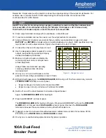
22. Use the designation labels (supplied) to record
outputs, as specified by operating company
standard installation procedures.
23. Make sure inputs at
loads are disabled
by
removing all power cards or all input fuses
at load equipment.
Always follow recommended operating
company guidelines when disabling
load equipment.
24.
One by one
, turn on circuit breakers on this
panel and check voltage and polarity at
input of loads.
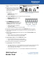
25. With all circuit breakers on, the
BREAKER ALARM
LED must go off. Test fuse alarm relay contacts
at
FUSE ALARM
terminals on rear of panel:
•
Expect continuity (0
Ω
)
between Terminals
C
and
NC
.
•
Expect an open circuit (
∞Ω
) between Terminals
C
and
NO
.
26. Switch off one of the circuit breakers to simulate a tripped breaker.
Again, the
BREAKER ALARM
LED should light.
27. Press ALARM RESET on front of panel.
The
BREAKER ALARM
LED should go off again. (Pressing ALARM RESET will reset the
BREAKER
ALARM
LED on front and clear
FUSE ALARM
on rear of panel.) Recheck the
FUSE ALARM
terminals and expect the same status as in step 25 with all breakers on.
28. If desired, connect remote external audio/visual alarm indicator wires (solid or tinned wires, #30 to
#16 AWG) to the
POWER FAIL
and
FUSE ALARM
terminals.
29. One by one, re-enable load equipment and verify proper operation.
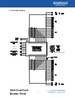
Figure 8 – Designation Label


