


Page 27
FIREFINDER SERIES II
INSTALLATION,
COMMISSIONING
&
OPERATION
7
The Main Menu
The
MAIN MENU
is accessed by pressing MENU.
FUNCTION
MENU
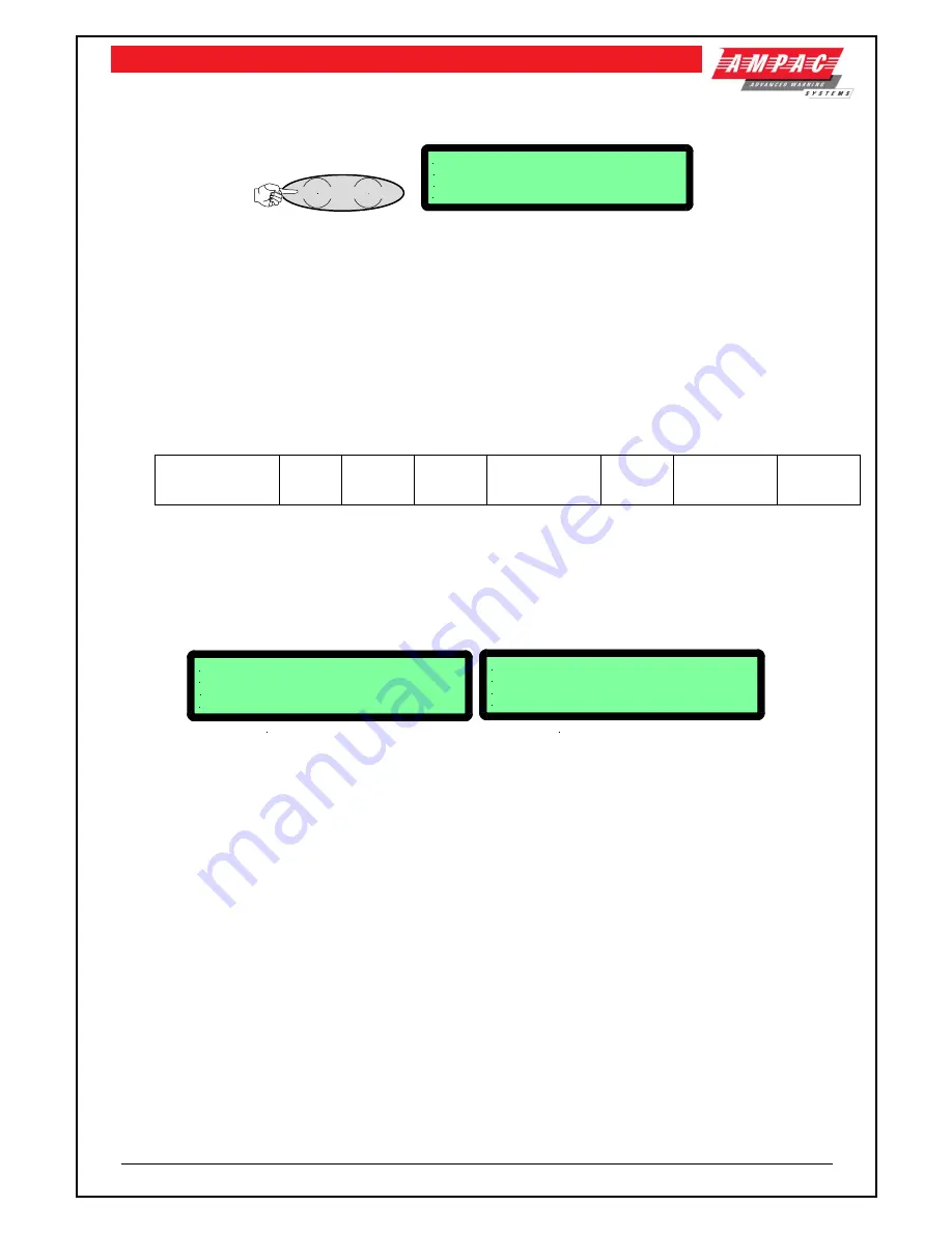
MAIN MENU
0: ALARMS 1:PREALARMS 2: FAULTS
3:ISOLATES 4: STATUS 5:TEST
SELECT NO.
Figure 29: The Main Menu
Numbering System:
denotes the menu structure number and
denotes the sub-menu
numbering.
Pressing the appropriate number on the keypad while in the MAIN MENU the user can view any;
FIRE ALARMS
PRE-ALARMS
FAULTS
; Pressing
brings up a sub-menu from which a more detailed description of the
fault can be displayed. With a Fault present select a field (
to
) to view details of the fault.
Zones Sensors
Loops
Modules
Comms
Power Supply
Brigade
Test Failures
Sounders
ISOLATES
on the system.
If there are no alarms, pre-alarms, faults or isolates, a message, e.g. NO ZONES OR SENSORS IN
ALARM will be displayed for 1 to 2 seconds and then the display will return to the Main menu.
7.1
Status Menu
Is pressed to access the STATUS MENU.
STATUS MENU
0: LOOPS 1: MODULES 2: I/O
3: SYSTEM 4:AVALUES
SELECT NO.
STATUS MENU
0: LOOPS 1: MODULES 2: I/O
3: NETWORK 4: SYSTEM 5:AVALUES
SELECT NO.
FACP WITH NETWORKING
FACP WITHOUT NETWORKING
Figure 30: The Status Menu
From the STATUS MENU the status of system components and settings can be selected and
displayed as listed below. Note that different screens are displayed for a system with and without
networking.
Press
Loops:
Enter the loop number and the LCD will display its status, e.g. normal, type of fault
etc.
Press
to print all devices on the loops (
Press
RESET to stop printing)
Press
to print totals of the loops (
Press
RESET to stop printing)
Modules:
Select the type of module, Slave
, P/S
, Brigade
or External LED
Mimic
and follow the screen prompts to display the status of the selected field.
I/O:
The LCD will display the status of an input or output in a panel or on a loop.
Press
to display Output status
–
IN A PANEL or
ON A LOOP
Press
to display Input status -
–
IN A PANEL or
ON A LOOP


