background image

Troubleshooting 

AQUATRAN 3/38 Operator’s Manual 


8-2 

Revision G 

MOCON, Inc. 

Recovering from a Sensor Over-Range Condition 


A severe over range condition will terminate the test sequence on both cells. 


If you see a red Cartridge Status indicator (on the front of the instrument), the test has failed due to a 

permeant sensor over-range condition. In addition to the red Cartridge Status indicator, an error indicator 

may be displayed on the Home screen. 


Examine the data on the Cell Status screen to determine the cause of the over-range condition. The Cell (or 

Cells) that caused the over-range will be “Failed”. If the ReZero Cell failed due to an over-range condition all 

active tests will be failed. 


Possible causes may be: 


The sample has a high transmission rate. To correct the problem testing can be done using a 

lower water vapor concentration test gas or a foil mask. 


The sample has pinholes, cracks or a poor-sealing surface. 


The cartridge is installed and clamped but no barrier is present. 


The o-ring seals on the top of the Test Cell are missing or damaged. 


After correcting the cause of the malfunction restart the test on the failed cell (or cells). 


Recovering from a Power Failure 


The instrument software records data at periodic intervals. This data is used to assist in recovering from 

power failures and instrument restarts. 


If testing is interrupted after the instrument has restarted testing will resume from the point at which it was 

interrupted. 


Содержание mocon AQUATRAN 3/38

Страница 1: ...Revision G Part Number 143 216 AQUATRAN 3 38 Operator s Manual Gas Detection Lauper Instruments AG Irisweg 16B CH 3280 Murten Tel 4126 672 30 50 info lauper instruments ch www lauper instruments ch...

Страница 2: ...atents MOCON and AQUATRAN are registered trademarks of MOCON Inc For information on applicable patents see https www ametekmocon com aboutus legal intellectualproperty Copyright 2021 MOCON Inc All rig...

Страница 3: ...ystem Works 1 Get an overview of the system See Chapter 1 Introduction on page 1 1 in this manual 2 Learn how the AQUATRAN measures water vapor transmission See Appendix D Theory of Operation on page...

Страница 4: ...d plumbing contamination use only specified gas type at recommended operating pressure Use only HPLC grade water in the humidity generator Use care to avoid splashing the RH sensor with any salt solut...

Страница 5: ...Connecting the Gas Lines 2 8 Setting the Gas Supply Pressure 2 9 System Outgassing 2 9 Chapter 3 Preparing for a Test 3 1 Testing Basics 3 1 How Barrier Properties Affect Testing 3 1 Testing Mixed Bar...

Страница 6: ...er 7 Maintenance 7 1 Cleaning the Instrument 7 1 Cleaning the Air Filters 7 2 Cleaning the Test Cells 7 3 Maintaining the Test Cells 7 3 Drying Out the Humidifier 7 3 Test Cartridge Components and Par...

Страница 7: ...sure D 3 Relative Humidity D 3 How a Humidified Test Gas is Generated D 4 How the ReZero Cell Works D 4 Appendix E Electrical and Plumbing Diagrams E 1 Appendix F Preparing RH Calibration Standards F...

Страница 8: ...11 Figure 7 1 The Air Filters 7 2 Figure 7 2 Test Cartridge Components 7 4 Figure 7 3 The Desiccant Chamber 7 7 Figure 9 1 Plumbing Diagram Page 1 E 2 Figure 9 2 Plumbing Diagram Page 2 E 3 Figure 9 3...

Страница 9: ...AQUATRAN 3 38 Water Vapor Transmission Rate System Read this chapter to get an overview of The features of the AQUATRAN 3 38 system A summary of basic steps in a permeation test A summary of how a Wat...

Страница 10: ...mounting Test Cartridges with TruSeal for increased performance Automatic control of Pressure Flow and RH Automatic control of the Test Cell Temperature QC Mode Advanced Gas Saver function reduces gas...

Страница 11: ...hen and how to use an Individual Zero Phase see Individual Zero Processing in Chapter 3 Conditioning the Sample Almost every material requires a period of time to acclimate to the environment and reac...

Страница 12: ...es or using an automatic convergence process When testing is complete the cell is removed from the test sequence and no further transmission rate examination of that sample is performed For more infor...

Страница 13: ...utside air from affecting the measurement The Test Gas is continuously applied to bottom half of the cell When performing a test using a 100 RH test gas the water vapor is supplied by a saturated spon...

Страница 14: ...he AQUATRAN 3 38 provides no capability for testing packages To test a film sample it is prepared and mounted in a Test Cartridge Both positions in the Test Cartridge referred to as the top and bottom...

Страница 15: ...ions Appendix A contain important information about preparing a location for the instrument and the facilities required for your new instrument Please read Appendix A before proceeding with the instal...

Страница 16: ...Revision G MOCON Inc Front Panel Parts and Controls The names and locations of the parts and controls located on the front of the instrument are shown in Figure 2 1 Figure 2 2 and Table 2 1 Figure 2 1...

Страница 17: ...AQUATRAN 3 38 Operator s Manual Setting Up MOCON Inc Revision G 2 3 15 9 10 14 13 11 12...

Страница 18: ...and gas vents 6 Instrument Display The color touch screen display used for instrument control 7 Cartridge Drawer Cartridge A The drawer which contains Test Cartridge A 8 Cartridge Drawer Cartridge B...

Страница 19: ...Up MOCON Inc Revision G 2 5 Back Panel Parts and Controls The names and locations of the parts and controls located on the back of the instrument are shown in Figure 2 3 and Table 2 2 Figure 2 3 Back...

Страница 20: ...e instrument on and off l is ON is OFF 4 Carrier Gas Inlet Port The fitting that connects the carrier gas supply to the instrument 5 Cooling Fan The fan that supplies cooling air to the sample heating...

Страница 21: ...tem Figure 2 4 illustrates how a gas distribution system for multiple instruments can be created using the provided Regulator Tee When using compressed gas cylinders consideration should be given to t...

Страница 22: ...of High Vacuum grease to four compression ferrules 5 Connect the Carrier Gas fitting on the instrument back panel to one side of the particulate filter 051 791 using the shorter piece of tubing and t...

Страница 23: ...n the previous instrument to the regulator tee on the next instrument 16 Connect the previous Carrier Gas regulator tee to the next Carrier Gas regulator tee using two nuts and ferrules 17 Using the p...

Страница 24: ...within in the instrument Out gassing removes this residual water vapor from the system To out gas the system follow these steps 1 Verify the Gas Supply Pressure is set correctly see setting the Gas Su...

Страница 25: ...nges to the test methodology Any sample with a transmission rate within the range of the instrument as specified in Chapter 9 can be tested Additional consideration is advised when setting up tests fo...

Страница 26: ...characteristics of the barrier sample will be very helpful in choosing an appropriate methodology For specific information on how to set or adjust the Test Method parameters discussed in this section...

Страница 27: ...o processing the Permeant Driving Force is deliberately reduced to negligible levels The Permeant Driving Force is reduced by inserting a blocking foil in the cell Any water vapor that is picked up on...

Страница 28: ...ore detailed information on the Test Mode parameter see the Instrument Help system Choosing a Test Method There are three different ways to specify the parameters that determine how a permeation test...

Страница 29: ...loading unloading the test cartridges filling the water reservoir setting the initial test conditions and starting tests The operator has full control of all test parameters when the Advanced Test fu...

Страница 30: ...rted the Home screen is automatically displayed in the workspace The application contains eighteen additional screens which are organized according to their primary function or task These functions ca...

Страница 31: ...ion of the modules Shut down of the system Suspect your data is not correct Permeant Sensor Accuracy Check The accuracy of the permeant sensor can only be checked by using a film to generate a referen...

Страница 32: ...etting up a film test The data from the test can then be used to adjust the permeant sensor After suitable data is available the WVTR Calibration screen can be used to adjust the output of the Permean...

Страница 33: ...e Test Cartridge from the instrument 3 Mount the Certified Film or reference film sample in the Test Cell For information on mounting films see Mounting Samples on page 6 7 4 Replace the test cartridg...

Страница 34: ...ndividual Zero phase was used set the Individual Zero control to the On position Set the Individual Zero Mode parameter to Beginning 9 After the film has been mounted and test parameters correctly ass...

Страница 35: ...ou in the day to day operation of your instrument Test duplicate samples whenever possible Use good samples Pinholes and creases can contribute to false readings Use caution when recording data for a...

Страница 36: ...m samples Special Cartridge for Thick Samples For samples with thickness up to 1 8 a specially designed cartridge with two side by side 10cm2 cells or with two side by side 5cm2 cells can be used Refe...

Страница 37: ...ple is thin less than 5 mils you need only mask one side Mount the sample in the test cell with the film side facing up If your sample is thicker than 5 mils mask both sides Be sure the mask apertures...

Страница 38: ...with the metalized side towards the carrier gas to prevent oxidation Using a 100 RH Test Gas The AQUATRAN 3 38 has the capability of using a 100 RH Test Gas A saturated sponge is used to generate a 10...

Страница 39: ...r to perform the test 3 Fill a syringe with HLPC grade water and attach short piece of tubing to the luer fitting 4 Push the end of the tubing onto the Fill Drain Port fitting 5 Open the Fill Valve by...

Страница 40: ...d RH testing are illustrated in the figure and table below Figure 6 1 Humidifier Fill Ports Item Name Description 1 Water Reservoir Test Gas Window showing the Test Gas Reservoir water level 2 Water F...

Страница 41: ...plates from the Film Mounting Plate middle part 3 Remove the old film samples from both sides of the Film Mounting Plate 4 Clean the film sealing surfaces of the Film Mounting Plate to remove the old...

Страница 42: ...Testing Film Samples AQUATRAN 3 38 Operator s Manual 6 8 Revision G MOCON Inc Figure 6 2 Mounting a Film Sample Bottom Position...

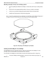
Страница 43: ...Film Mounting Plate Note Inspect the gap between the top and bottom Test Gas Plates and the Film Mounting plate If the gap is not even on all four sides one of the O Rings may not be properly seated...

Страница 44: ...Test Cartridge into the instrument follow the instructions below refer to Figure 6 4 and 6 5 1 Grasp the Test Cartridge by the front and back edges and lower it straight down 2 Close the Cell Cartridg...

Страница 45: ...e Test icon is used to access the screens and controls required to set up the test conditions and start a test There are two methods that can be used to setup a permeation test A test can be setup usi...

Страница 46: ...sing the Home Cell Status and Instrument Status screens These screens are accessed by selecting the Home and Status icons As each phase or state in a test is completed the test will automatically be a...

Страница 47: ...Instrument The AQUATRAN 3 38 is housed in a painted metal and plastic case that is easy to clean and maintain Periodically wipe the case with a damp cloth and mild detergent solution Warning Turn OFF...

Страница 48: ...ecommended interval is twice a year or whenever there is a significant buildup of dust If the filter is not cleaned on a regular basis air will not circulate properly through the cooling system The pe...

Страница 49: ...cratch is a simple way to estimate the depth of the flaw Nicks and scratches deep enough to feel may cause errors in the transmission rate due to leakage Drying Out the Humidifier Before shutting down...

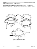
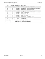
Страница 50: ...omponents and Part Numbers The parts of the test cartridge are shown in Figure 7 2 below Refer to Table 7 1 for the associated part numbers and the quantity used To order replacement parts contact MOC...

Страница 51: ...Ring 0 087 ID X 0 040 CS Buna N 70 Durometer 3 3 050 112 O Ring 0 145 ID X 0 070 CS Viton 4 2 052 185 O Ring 3 661 ID X 0 050 CS Buna N 5 1 054 070 Cell Test Bottom HT 6 1 054 071 Cell Test CG HT 7 1...

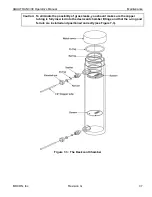
Страница 52: ...n spring and o ring from the chamber 5 Empty the desiccant from the chamber 6 Clean the chamber thoroughly with water and let it dry 7 Fill the chamber slightly less than halfway with molecular sieve...

Страница 53: ...7 Caution To eliminate the possibility of gross leaks you should make sure the copper tubing is fully inserted into the desiccant chamber fittings and that the o ring and ferrule are installed and po...

Страница 54: ...o 50 System Shutdown for Storage or Repair When shutting down the instrument for relocation long term storage or if the instrument is to be sent for factory repairs follow these instructions 1 End all...

Страница 55: ...roblem write down both the error code and the message This will help MOCON service representatives diagnose the problem Contact MOCON in the USA at 763 493 6370 Troubleshooting Testing Problems The fo...

Страница 56: ...led due to an over range condition all active tests will be failed Possible causes may be The sample has a high transmission rate To correct the problem testing can be done using a lower water vapor c...

Страница 57: ...2 inches 30 4 cm 23 inches 58 0 cm 95 pounds 43 1 kg Crated 25 inches 63 5 cm 19 inches 48 3 cm 37 inches 94 cm 115 pounds 52 2 kg Table 9 1 Physical Specifications Environmental Requirements Temperat...

Страница 58: ...Requirements Voltage 100 240 VAC 50 60 Hz Maximum Power Draw 700 VA Current Draw at 100 VAC 50 Hz 1 80 A nominal Current Draw at 120 VAC 60 Hz 1 50 A nominal Current Draw at 220 VAC 50 Hz 0 82 A nomin...

Страница 59: ...ntrol Range 20 C to 40 C 0 2 C Time to Reach a Heated Temp from ambient Approximately 60 minutes to reach 99 of a 40 C setting Humidity Control Film Cell Test Gas 100 and 50 to 90 RH 3 RH RH Film Cell...

Страница 60: ...utes Certified Film P N 054 163 Red 0 05 g m2 day 0 05 to 10 gm m2 day 0 0032 to 0 645 gm 1002 day 0 00025 to 0 05 gm pkg day 10 sccm 45 minutes Certified Film P N 054 164 Blue 2 0 of Reading or 0 05...

Страница 61: ...AQUATRAN 3 38 Operator s Manual Site Preparation Instructions MOCON Inc Revision G A 1 Appendix A Site Preparation Instructions P N 140 223 See next page...

Страница 62: ...nches should be sufficiently large and strong to accommodate the instrument and printer in close proximity 2 ENVIRONMENTAL REQUIREMENTS The AQUATRAN 3 38 should be operated in an environment with a st...

Страница 63: ...hing else that is needed 7 COPPER TUBING Metallic tubing is required for connecting the nitrogen supply to the rear panel of the instrument Desiccated and sealed D S refrigeration grade copper tubing...

Страница 64: ...installed in the AC line to the system by a qualified electrician A noisy circuit or improper grounding will cause adverse performance and possible damage to the system WARNING The installation of the...

Страница 65: ...EA 027 343 Regulator Tee Tested 1 EA 027 790 Regulator N2 HE Two Stage High Purity CGA 580 1 EA 028 538 Sponge Test Head 10 EA 030 802 Flask Erlenmeyer 250 ml Narrow Mouth Heavy Duty Rim 1 EA 030 803...

Страница 66: ...unting Holes 10 EA 143 216 Manuscript AQUATRAN 3 38 On Flash Drive 1 EA 210 017 Cord Power 125V 18 3 SVT IEC Unshielded 7 1 2 FT 1 EA 310 027 Nut 1 8 Tube Brass 10 EA 310 051 Ferrule 1 8 Tube Brass 10...

Страница 67: ...anty and Service Policies MOCON Inc Revision G C 1 Appendix C Warranty and Service Policies Part Number 032 846 Warranty Policy Part Number 032 847 International Service Policy Part Number 032 848 Dom...

Страница 68: ...o Coulox and IR Sensors in the following Instruments have an extended warranty as defined below AQUATRAN 2 22 2 28 2 40 2 48 PERMATRAN W 3 34 PERMATRAN C 4 30 AQUATRAN 3 38 3 40 together the Extended...

Страница 69: ...or special damages or losses arising out of the purchase of the Product and or out of this limited warranty even if MOCON or its designated representative have been advised of the possibility of such...

Страница 70: ...premises are free of charge subject to warranty restrictions PART REPLACEMENT If a local service representative is not available in country and if a defective part can be determined by the Customer s...

Страница 71: ...ERFORMED AFTER WARRANTY PERIOD In the event that repairs are required after the warranty period the Purchaser again has several alternatives PREVENTIVE MAINTENANCE CONTRACT Preventive maintenance cont...

Страница 72: ...eapolis Minnesota freight and Insurance will be billed separately MOCON insures all shipments unless advised otherwise All repairs after the original instrument warranty period are warranted for 90 da...

Страница 73: ...ared Detector The measurement system consists of a bellows pump a sensing chamber an infrared source a 2 6 micrometer infrared filter a lead sulfide photo detector and an amplifier The pump varies the...

Страница 74: ...puter subtracts the ReZero value from the DC output value The result is converted to units of Water Vapor Transmission Rate WVTR using a scaling factor determined by the nitrogen gas flow rate Factors...

Страница 75: ...ed by changes in the barometric pressure The instrument automatically compensates all transmission rate data to eliminate the effect of barometric pressure on the reported transmission rate Relative H...

Страница 76: ...of water vapor ingress This includes the system baseline If the system baseline can be measured subtracting it from the apparent transmission rate of the test cell will give a more accurate representa...

Страница 77: ...erator s Manual Electrical and Plumbing Diagrams MOCON Inc Revision G E 1 Appendix E Electrical and Plumbing Diagrams Title Part Number Plumbing Diagram AQUATRAN 3 38 051 953 Electrical Diagram AQUATR...

Страница 78: ...Electrical and Plumbing Diagrams AQUATRAN 3 38 Operator s Manual E 2 Revision G MOCON Inc Figure 9 1 Plumbing Diagram Page 1...

Страница 79: ...AQUATRAN 3 38 Operator s Manual Electrical and Plumbing Diagrams MOCON Inc Revision G E 3 Figure 9 2 Plumbing Diagram Page 2...

Страница 80: ...Electrical and Plumbing Diagrams AQUATRAN 3 38 Operator s Manual E 4 Revision G MOCON Inc Figure 9 3 Electrical Diagram Page 1...

Страница 81: ...AQUATRAN 3 38 Operator s Manual Electrical and Plumbing Diagrams MOCON Inc Revision G E 5 Figure 9 4 Electrical Diagram Page 2...

Страница 82: ...Electrical and Plumbing Diagrams AQUATRAN 3 38 Operator s Manual E 6 Revision G MOCON Inc Figure 9 5 Electrical Diagram Page 3...

Страница 83: ...esult in frostbite or burn injuries Salt solutions should be prepared only by qualified people with proper safety equipment RH sensor calibration will be performed at a specific temperature A salt mus...

Страница 84: ...ome to equilibrium at the desired temperature before use Preparing a Low Level Calibration Standard A Low Level RH Calibration standard can be prepared using a molecular sieve as follows 1 Thoroughly...

Страница 85: ...AQUATRAN 3 38 Operator s Manual Compliance MOCON Inc Revision G G 1 Appendix G Compliance...

Отзывы: