STRATOS VERTICAL PLATFORM LIFTS:
Install Manual
04DEC2020 | 630-00147 REV A
20
INSTALLATION
STRATOS: SECTION 4
OPERATIONAL CHECK
Upon installation and at scheduled intervals the
operation of the VPL must be verified.
NOTE: ASME A18.1-2017 requires that when the lift is
installed in commercial applications, operation checks
are to be conducted not less than weekly by authorized
personnel.
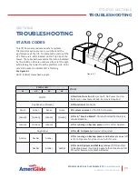
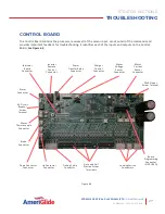
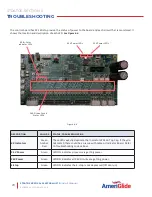
Apply power and verify all four (4) LED
indicator lights are solid green.
Paddle/buttons on cab controls control UP
and DOWN travel.
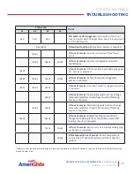
E-Stop PRESSED IN stops and prevents travel
of platform. Button illuminates and alarm
sounds (if equipped). Indicator lights 1, 2, 3
and four (4) are solid RED.
Key switch (if equipped) OFF stops and
prevents travel.
Landing switches stop the platform at each
landing within 1/2", does not coast, and
opens the gate locks.
Automatic Door Openers (if equipped) open
the doors/gates at landing.
Open doors/gates prevents any travel of the
platform. Indicator lights three (3) and four
(4) are solid RED.
Call Station buttons control UP and DOWN
travel.
Key switch (if equipped) OFF on Call Stations
stops and prevents travel from Call Station.
Safety pan switches depressed prevent
DOWN travel and allow UP travel (check
several locations). Indicator lights one (1)
and (2) are flashing AMBER.
Pit switch (if equipped) prevents UP and
DOWN travel. Indicator lights 1, 2 and 3 are
solid RED
PERMANENT POWER
INSTALLATION
Permanent power can be installed at various points
in the overall installation process; however it must
be installed by a qualified electrical contractor in
compliance with local codes and regulations. Power
must be a dedicated circuit connected through a
2-pole fused and lockable disconnect. Fuse should
be a minimum of 15A.
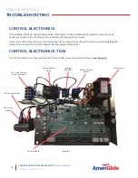
Route wiring from disconnect to tower as directly as
possible and enter tower through most convenient
knock-out in tower side panels. Inside the tower
enclosure route wires from knockout to internal
junction box along the back panel of the enclosure.
Use the back side of the wire channel if the junction
box is at a different level than knockout. Be sure all
wiring is routed clear of the moving carriage and
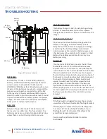
roller wheels inside the tower. See Figure 4-14.
Knockout
Wire Channel
Junction Box
Figure 4-14


