STRATOS VERTICAL PLATFORM LIFTS:
Install Manual
04DEC2020 | 630-00147 REV A
19
INSTALLATION
STRATOS: SECTION 4
INSTALLATION TOWER
CHECK
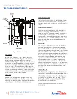
Before reinstalling the top cap and front panels,
an operational check should be completed on the
internal tower safety features.
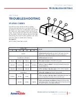
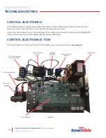
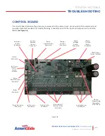
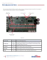
Apply temporary power and verify all four
(4) LED indicator lights on the control board
are solid green.
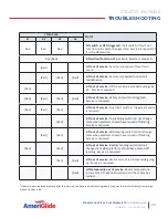
Manually depress the final limit switch
(the highest positioned switch) and verify
any travel of platform is prevented and
indicator lights 1, 2 and 3 are flashing RED.
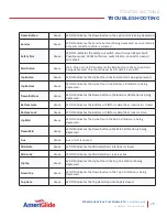
Manually depress the safety nut switch
(the switch near ACME nut) and verify
any travel of platform is prevented and
indicator lights 1, 2, 3 and 4 are flashing
RED.
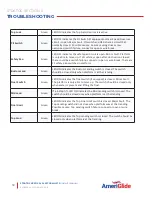
Manually depress the Over-Speed Governor
(OSG) switch (the switch at the bottom
of ACME screw) and verify any travel of
platform is prevented and indicator lights
1, 2 and 3 are solid RED.
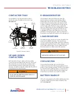
If equipped, lift the float of the float switch
(the switch at the bottom of tower) and
verify that DOWN travel is prevented and
indicator light two (2) is flashing AMBER.
Verify that the ACME drive screw is
lubricated.
Verify that the shipping bolt was removed
from the cable tensioning pulley and that
the pulley is hanging in the tower without
hitting any obstacles during platform
travel.
Verify that the manual lowering wrench
and socket are in place and secured on the
top plate with wing nuts.
Verify that the E-Stop is functional and
all 4-LED lights are solid red with no lift
movement.
Verify the screws securing the tower skins
have a plastic washer and are tight.
Reset the board
❑
Enter service mode by pressing and
releasing the service button
❑
Press and hold down the service
button again for 3-seconds.
❑
Press and release the reset button.
FINAL INSTALLATION
Completing the above steps will clear any errors
from the board.
1. Install the front panel between the platform
and tower. Slots in the bottom of front panel
should rest on the pins in the tower. Install
five (5) ¼"-20 screws and plastic washers at
top front panel leaving top three (3) screws
loose and ¼" offset from panel.
2. Disconnect the power to the lift. Connect
the cable in the top cap for status indicator
lights into the control board. Slide the top
cap over top of the tower aligning the top
cap slots with the four (4) side screws and
three (3) front screws. There are tabs in the
back of the top cap that drop into slots in the
tower top plate. These tabs must drop into the
slots for the top cap to sit down on all seven
(7) screws. Tighten seven (7) ¼"-20 screws
securely against the top cap. Reconnect the
power to the lift.


