background image

Chapter 5     


51 

Chapter 5  How to update your BIOS? 


Updating BIOS may result an unstable system. All the data of the old BIOS 

will be replaced by the new BIOS. Should anything go wrong during the 

updating process, your system would end up crashed. Please refer to your 

supplier or manufacture for more support. PLEASE DO NOT UPDATE YOUR 

BIOS UNTIL YOU HAVE CAREFULLY READ THE FOLLOWING INSTRUCTIONS.


Update Your System BIOS 

1. 

Find out the exact model name of your motherboard 

There are different updates for different versions of your motherboard. For 
example, the 9LIF0 uses different BIOS than the 9LIF1. You will need to know 
whether your motherboard is a `0` or `1` version (or higher). You can find the 
model name on the motherboard, which is written between or around one of the 
PCI slots. 

2. 

Obtain the latest BIOS update. 

Obtain the latest BIOS update from supplier or form the manufacture. You can 
refer to there website for the latest version of BIOS. 

3. 

Use the correct FLASH utility 

The FLASH utility has many versions. It is recommended to use the version that 
came with your motherboard. Only when you experience problems updating the 
BIOS or if you do not have the FLASH utility, then you can download one of the 
versions available on the Internet. 

4. 

Disable the FLASH BIOS Protection in the BIOS 

Some motherboards have


[Flash BIOS Protection] option in the BIOS [CHIPSET 

SETUP]. Please [

Disable

] the option before attempting to update the BIOS. 

5. 

Unpack the BIOS Update file 

The file you downloaded in step 2. is most likely to be an executable file. (*.EXE) 
You can only update your BIOS using a binary file (*.BIN). Unpack the file by 
clicking its name. The file should automatically unpack into the binary file. 

6. 

Startup your system under DOS without any TSR's installed 

The FLASH utility can only work well when there are no memory drivers or other 
TSR's installed. It is recommended to start up your system from a floppy disk, (run 
FORMAT A: /S under DOS to create a start up disk which only has the system 
COMMAND.COM); or press F8 to bypass the AUTOEXEC.BAT and 
CONFIG.SYS startup files. 

7. 

Run the FLASH utility 

Make sure the BIOS update binary file is in the same directory as the FLASH 
utility. Remember the exact name of the BIOS update file. (Please pay attention to 

Chapter 5   


52 

`0`(zero) and o (letter `O`)). Then run the flash utility. 
On the screen the program will ask for the [File Name to Program]. Type in the 
exact name of the BIOS update binary file, including the *.BIN, and press 
[

ENTER

]. The program will now ask you if you want to save your current BIOS 

version. Choose  [

ENTER

] and type a filename for your current BIOS 

version, for example OLDBIOS.BIN.   
Press [

ENTER

] and the program will save the current BIOS data to your current 

path. Now the program will ask you to confirm your wish to update the BIOS using 
the file you mentioned earlier. Press [

Y

] to confirm. 

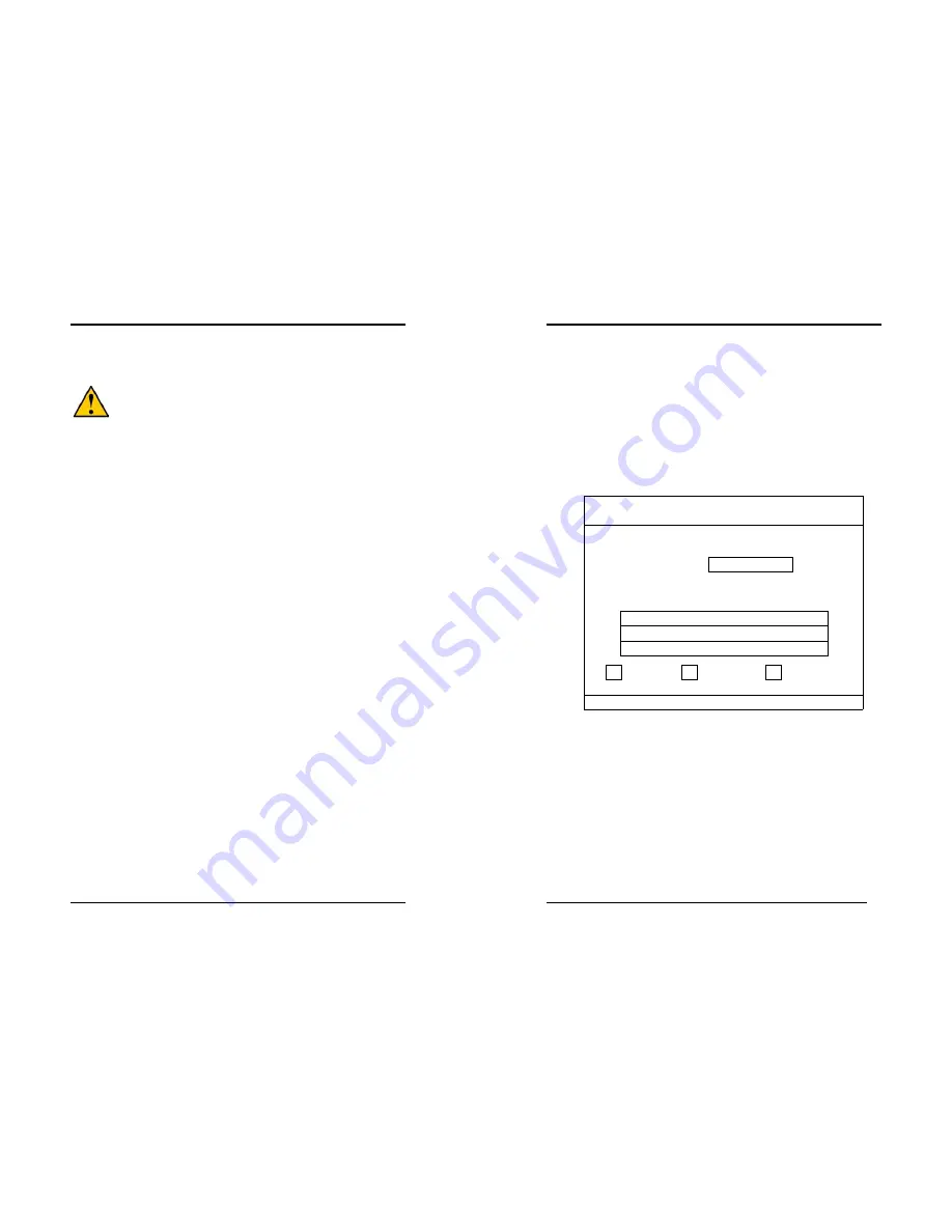
The updating process will now start. Screens bellow will appear which indicates 
the progress of the updating process. 

Award BIOS Flash Utility V X.XX 

(C) Phoenix Technologies Ltd. All Right Reserved


For XXXX-XXXXXX-XXXXXXXXXX-X   DATE: XX/XX/2002 
Flash Type- XXXXXX XXXXXXXX / 3.xV (1MB) 
File Name to Program: 
 
Programming Flash Memory 


XXXXXXXX.BIN 


Write OK 


No Update 


Write Fail 

Warning : Don’t Turn Off Power Or Rest System 


8. 

Wait until the system finishes the updating process and the message: [

Please 

Power Off Or Reset System!

] appears. 

Now you can power off your system. Wait for a few seconds and turn on your 
system again. You should now be able to see the new BIOS date code appearing in 
the left upper corner of the screen. 

Содержание 7NIF2

Страница 1: ...ing two conditions 1 This device may not cause harmful interference 2 This device must accept any interference received including interference that may cause undesired operation This declaration is gi...

Страница 2: ...s subject to change without notice and does not represent a commitment on the part of the vendor No warranty or representation either expressed or implied is made with respect to the quality accuracy...

Страница 3: ...i Word Mode 6 up to 133MBps with bus mastering Bus Mastering software drivers for all common multi task operating systems USB 2 0 1 0 Host Controller One EHCI USB 2 0 controller and 2 OHCI USB 1 1 con...

Страница 4: ...Chapter 1 3 1 3 7NIF2 Motherboard Diagram Chapter 1 4 1 4 7NIF2 Motherboard Layout...

Страница 5: ...e CPU to push itself into place Do not apply extra pressure as doing so may result in damaging your CPU Snap the lever back into place Installing an AMD approved heat sink with cooling fan is necessar...

Страница 6: ...Rate DDR Dual Inline Memory Modules DIMM slots Which supports PC 1600 DDR200 PC2100 DDR266 PC2700 DDR333 and PC3200 DDR400 DDR SDRAM modules up to 3GB To support Dual Channel DDR400 please use an add...

Страница 7: ...are used to link the system board with other parts of the system including the power supply the keyboard and the various controllers on the front panel of the system case The power supply connector i...

Страница 8: ...being disconnected for a certain period of time the poly fuse will return to its normal state Then the keyboard or USB connector can function properly again Unlike conventional fuses the poly fuse doe...

Страница 9: ...efaults Type Y and then press Enter to continue 5 Set the system configuration in the Standard CMOS Setup menu Pin Definition 1 2 Normal default 2 3 Clear CMOS Data Chapter 2 14 JP5 Keyboard Power On...

Страница 10: ...ncy 1 2 The default value is 133 166 MHz The will allow the CPU s Ext Frequency and memory frequency to be adjusted through the BIOS 2 3 Set 100 MHz at CPU Ext frequency The will allow the Memory freq...

Страница 11: ...fferent ways as defined by Power Management Setup screen in BIOS 4 RESET System Reset Switch Connector This connector should be connected to the reset switch on the front panel of the system case The...

Страница 12: ...es WOL capability to the motherboard CN5A WOM Wake on Modem Connector The Wake Up On Modem selection in BIOS s Power Management Setup Menu must be enabled to use this function This header is used to c...

Страница 13: ...tains a USB Host controller and includes a root hub connector for optional USB Adaptor USB 2 3 and 4 5 Chapter 2 22 CN24 Front Audio Connector This connector give you the option of a front panel audio...

Страница 14: ...asic system configuration This information is stored in CMOS RAM so that it can retain the setup information even when the power is turned off To enter the Phoenix Award BIOS setup program press the D...

Страница 15: ...orms a series of diagnostic tests called POST Power On Self Test This function stops the computer if BIOS detects a hardware error You can tell BIOS to halt on all errors no errors or not to halt on s...

Страница 16: ...c Delay Msec The typematic delay sets how long after you press a key that a character begins repeating Security Option The Supervisor and or User Password functions shown in Figure 3 1 must be set to...

Страница 17: ...Select this option will let the system automatically detect its performance Aggressive Select this option for a better system performance It increases a bit of the system performance Memory Frequency...

Страница 18: ...protection technology that protects the System BIOS from accidental corruption by unauthorized users or computer viruses When enabled the BIOS data cannot be changed when attempting to update BIOS wi...

Страница 19: ...ou to select an operating mode for the second serial port Available options are Normal IRDA ASKIR and SCR 4 UR2 Duplex Mode This allows you to adjust the way of Infer Red transmitting Available option...

Страница 20: ...er and the monitor s electron gun turns off This function requires a monitor with Green features in order to take advantage of the power saving function If you enable this function and do not have a G...

Страница 21: ...RQ and DMA setting information By choosing the PNP PCI Configuration option from the CMOS Setup Utility menu Figure 3 1 the screen below is displayed This screen contains the manufacturer s default va...

Страница 22: ...quency Voltage Control By choosing the Frequency Voltage Control option from the CMOS Setup Utility menu Figure 3 1 the screen below is displayed This sample screen contains the manufacturer s default...

Страница 23: ...et to Setup a password is required to enter BIOS and change BIOS settings When the Security Option function is set to System a password is required to enter both BIOS and the computer s operating syst...

Страница 24: ...ver Package to begin installation 2 Please click NEXT to start installation Chapter 4 44 3 Please click OK to continue 4 To restart you computer now select Yes I want to restart my computer now then P...

Страница 25: ...Please click NEXT to start installation Chapter 4 46 3 To restart you computer now select Yes I want to restart my computer now then Please Click OK to restart you computer If you do not want to rest...

Страница 26: ...Please select Audio Drive to begin installation 2 Please click NEXT to start installation Chapter 4 48 3 Please click Next to continue install the C Media Audio driver 4 Please click Next to continue...

Страница 27: ...then click OK to continue 4 4 USB 2 0 Driver Setup By Choosing USB 2 0 Driver from the main menu it will provide the information that you require to install the USB 2 0 Drive For Windows XP 2000 inst...

Страница 28: ...o the binary file 6 Startup your system under DOS without any TSR s installed The FLASH utility can only work well when there are no memory drivers or other TSR s installed It is recommended to start...

Страница 29: ...604 497645 Fax 44 0 1604 491898 E Mail phil follett eelt chaintechuk com For China CHAINTECH SHENZHEN Room 301 No 1004 Huafu road Shenzhen Tel 86 755 8368 9072 Fax 86 755 8368 9072 CHAINTECH BEIJING A...

Отзывы: