background image

Chapter 3     


29 

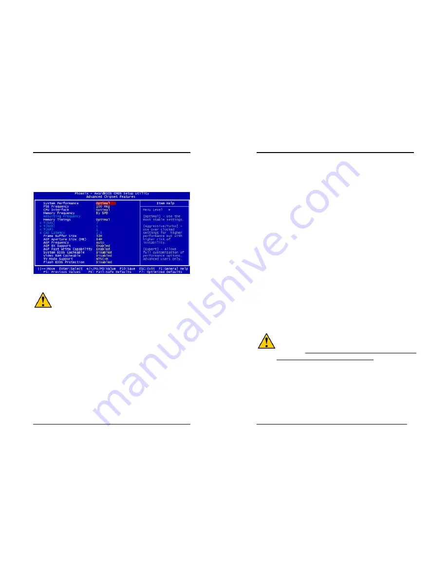
3-3 Advanced Chipset Features 

By choosing the [

Advanced Chipset Features

] option from the CMOS Setup Utility 

menu (Figure 3-1), the screen below is displayed. This sample screen contains the 
manufacturer's default values for the motherboard. 


Figure 3-4 Advance Chipset Features Screen 


All of the above settings have been determined by the motherboard 
manufacturer and should not be changed unless you are absolutely sure of 
what you are doing. Explanation of the DRAM timing and chipset features 
setup is lengthy, highly technical and beyond the scope of this manual. Below 
are some abbreviated descriptions of the functions in this setup menu. 

System Performance. 

This option allows you to configure and determine your systems performance 
according to your needs. Available options are: [

Optimal

], [

Aggressive

], [

Turbo

] and 

[

Expert

], there details are as follows: 

Optimal: 

Select this option will let the system automatically detect its performance. 

Aggressive: 

Select this option for better system performance. It increases a bit of the 

system performance. 

Turbo:

 Select this option for a faster system performance. It will increase the system 

performance, but it might result in an unstable system. 

Expert: 

Select this option only if you are a professional user. This will allow you to 

manually adjust the system performance according to your needs. 

FSB Frequency 

This feature allows the configuration of systems FSB frequency speed. Available 
options include 

100 MHz 

(

200 MHz

) to 

200


MHZ 

(

400 MHz

)

Chapter 3   


30 

CPU Interface 

This option allows you to determine how your CPU interface performs. Available 
options are: [

Optimal

] and [

Aggressive

] there details are as follows: 

Optimal: 

Select this option will let the system automatically detect its performance. 

Aggressive: 

Select this option for a better system performance. It increases a bit of 

the system performance. 

Memory Frequency 

This option will allow you to adjust the Memory Frequency. Available options are [

By 

SPD

] or [

By Sync

], there details are as follow: 

By SPD: 

It automatically detects the memory frequency. 

By Sync: 

This will cause the memory to detect the CPU’s Ext. frequency and 

function synchronically. 

Memory Timing 

This function allows you to adjust the DRAM timing. Available options are: 
[

Optimal

], [

Aggressive

], [

Turbo

] and [

Expert

], there details are as follows: 

Optimal: 

Select this option will let the memory timing to automatically detect its 

performance. 

Aggressive: 

Select this option for better memory timing. It increases a bit of the 

system performance. 

Turbo:

 Select this option for faster memory timing. It will increase the memory 

timing, but it might result in an unstable system. 

Expert: 

Select this option only if you are a professional user. This will allow you to 

manually adjust the memory timing according to your needs. 


Overclocking:


This motherboard is designed to support overclocking. However, please make 
sure your components are able to tolerate such abnormal setting, while doing 
overclocking. Any attempt to operate beyond product specifications is not 
recommended. We do not guarantee the damages or risks caused by 
inadequate operation or beyond product specifications. 

Frame Buffer Size 

This function determines the amount of system memory that is allocated to the on 
board VGA. Options range from 

8MB

 to 

128MB

AGP Aperture Size (MB) 

This function determines the amount of system memory that is given to the AGP card.   
Options range from 

32MB

 to 

512MB

. This is a dynamic memory allotment in that the 

AGP card will only use the amount of memory that it needs. The remaining memory, 

Содержание 7NIF2

Страница 1: ...ing two conditions 1 This device may not cause harmful interference 2 This device must accept any interference received including interference that may cause undesired operation This declaration is gi...

Страница 2: ...s subject to change without notice and does not represent a commitment on the part of the vendor No warranty or representation either expressed or implied is made with respect to the quality accuracy...

Страница 3: ...i Word Mode 6 up to 133MBps with bus mastering Bus Mastering software drivers for all common multi task operating systems USB 2 0 1 0 Host Controller One EHCI USB 2 0 controller and 2 OHCI USB 1 1 con...

Страница 4: ...Chapter 1 3 1 3 7NIF2 Motherboard Diagram Chapter 1 4 1 4 7NIF2 Motherboard Layout...

Страница 5: ...e CPU to push itself into place Do not apply extra pressure as doing so may result in damaging your CPU Snap the lever back into place Installing an AMD approved heat sink with cooling fan is necessar...

Страница 6: ...Rate DDR Dual Inline Memory Modules DIMM slots Which supports PC 1600 DDR200 PC2100 DDR266 PC2700 DDR333 and PC3200 DDR400 DDR SDRAM modules up to 3GB To support Dual Channel DDR400 please use an add...

Страница 7: ...are used to link the system board with other parts of the system including the power supply the keyboard and the various controllers on the front panel of the system case The power supply connector i...

Страница 8: ...being disconnected for a certain period of time the poly fuse will return to its normal state Then the keyboard or USB connector can function properly again Unlike conventional fuses the poly fuse doe...

Страница 9: ...efaults Type Y and then press Enter to continue 5 Set the system configuration in the Standard CMOS Setup menu Pin Definition 1 2 Normal default 2 3 Clear CMOS Data Chapter 2 14 JP5 Keyboard Power On...

Страница 10: ...ncy 1 2 The default value is 133 166 MHz The will allow the CPU s Ext Frequency and memory frequency to be adjusted through the BIOS 2 3 Set 100 MHz at CPU Ext frequency The will allow the Memory freq...

Страница 11: ...fferent ways as defined by Power Management Setup screen in BIOS 4 RESET System Reset Switch Connector This connector should be connected to the reset switch on the front panel of the system case The...

Страница 12: ...es WOL capability to the motherboard CN5A WOM Wake on Modem Connector The Wake Up On Modem selection in BIOS s Power Management Setup Menu must be enabled to use this function This header is used to c...

Страница 13: ...tains a USB Host controller and includes a root hub connector for optional USB Adaptor USB 2 3 and 4 5 Chapter 2 22 CN24 Front Audio Connector This connector give you the option of a front panel audio...

Страница 14: ...asic system configuration This information is stored in CMOS RAM so that it can retain the setup information even when the power is turned off To enter the Phoenix Award BIOS setup program press the D...

Страница 15: ...orms a series of diagnostic tests called POST Power On Self Test This function stops the computer if BIOS detects a hardware error You can tell BIOS to halt on all errors no errors or not to halt on s...

Страница 16: ...c Delay Msec The typematic delay sets how long after you press a key that a character begins repeating Security Option The Supervisor and or User Password functions shown in Figure 3 1 must be set to...

Страница 17: ...Select this option will let the system automatically detect its performance Aggressive Select this option for a better system performance It increases a bit of the system performance Memory Frequency...

Страница 18: ...protection technology that protects the System BIOS from accidental corruption by unauthorized users or computer viruses When enabled the BIOS data cannot be changed when attempting to update BIOS wi...

Страница 19: ...ou to select an operating mode for the second serial port Available options are Normal IRDA ASKIR and SCR 4 UR2 Duplex Mode This allows you to adjust the way of Infer Red transmitting Available option...

Страница 20: ...er and the monitor s electron gun turns off This function requires a monitor with Green features in order to take advantage of the power saving function If you enable this function and do not have a G...

Страница 21: ...RQ and DMA setting information By choosing the PNP PCI Configuration option from the CMOS Setup Utility menu Figure 3 1 the screen below is displayed This screen contains the manufacturer s default va...

Страница 22: ...quency Voltage Control By choosing the Frequency Voltage Control option from the CMOS Setup Utility menu Figure 3 1 the screen below is displayed This sample screen contains the manufacturer s default...

Страница 23: ...et to Setup a password is required to enter BIOS and change BIOS settings When the Security Option function is set to System a password is required to enter both BIOS and the computer s operating syst...

Страница 24: ...ver Package to begin installation 2 Please click NEXT to start installation Chapter 4 44 3 Please click OK to continue 4 To restart you computer now select Yes I want to restart my computer now then P...

Страница 25: ...Please click NEXT to start installation Chapter 4 46 3 To restart you computer now select Yes I want to restart my computer now then Please Click OK to restart you computer If you do not want to rest...

Страница 26: ...Please select Audio Drive to begin installation 2 Please click NEXT to start installation Chapter 4 48 3 Please click Next to continue install the C Media Audio driver 4 Please click Next to continue...

Страница 27: ...then click OK to continue 4 4 USB 2 0 Driver Setup By Choosing USB 2 0 Driver from the main menu it will provide the information that you require to install the USB 2 0 Drive For Windows XP 2000 inst...

Страница 28: ...o the binary file 6 Startup your system under DOS without any TSR s installed The FLASH utility can only work well when there are no memory drivers or other TSR s installed It is recommended to start...

Страница 29: ...604 497645 Fax 44 0 1604 491898 E Mail phil follett eelt chaintechuk com For China CHAINTECH SHENZHEN Room 301 No 1004 Huafu road Shenzhen Tel 86 755 8368 9072 Fax 86 755 8368 9072 CHAINTECH BEIJING A...

Отзывы: