background image

Chapter 2     


2-4  Connector and Jumper Reference Chart 

Jump Connector 

Function 

Page 

PW 1 

u-ATX Power Supply Connector 

10 

FD1 Floppy 

Connector 

11 

IDE 1/2 

IDE Hard-Disk Connector 

12 

FAN 1/3 

CPU/ Case FAN Connector (12V) 

12 

FAN 4 

North Bridge Cooling Fan Power Connector    (12V) 

13 

JP1 

CMOS Clear Jumper 

13 

JP5 

Keyboard Power on Function Jumper 

14 

JP6 

Disable/Enable USB 0/1 Device Power ON Jumper 

14 

JP6A /B 

Disable/Enable USB 2/3,4/5 Device Power ON Jumper 

15 

JP23 

Green LED Mode Jumper 

15 

JP25 

Setup CPU FSB. Freq. Jumper 

16 

CN1A 

Front Panel (Power / Rest / SPK…etc.) Connector 

16 

CN2 /2A 

CD-ROM Audio-in Connector 

17 

CN3 Auxiliary 

Audio-in 

Connector 

18 

CN4C SPDIF 

KIT 

Connector 

18 

CN5 

Wake on LAN Connector 

19 

CN5A 

Wake on Modem Connector 

19 

CN7 

Smart Card Reader Connector 

20 

CN9 

Chassis Open Alarm Connector 

20 

CN17 

Blue LED Connector (5V) 

21 

CN23 /23A 

USB Connector for USB 2/3 and 4/5 

21 

CN24 Front 

Audio 

Connector 

22 

COM1 

Serial port / COM Headers 

22 

COM2 

Serial port / COM Headers 

23 

IR2 

IR & CIR Connector 

23 

Chapter 2   


10 

2-5  Connector and Jumper Settings 

Connectors are used to link the system board with other parts of the system, 
including the power supply, the keyboard, and the various controllers on the front 
panel of the system case. 


The power supply connector is the last connection to be made while 
installing a motherboard. Before connecting the power supply, please make 
sure it is not connected to the power source. 


All cables are security-proof 

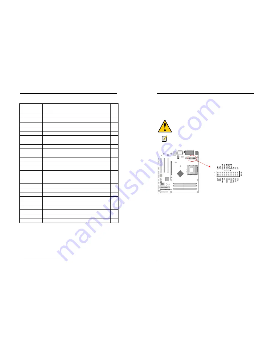
PW 1 (u-ATX Power Supply Connector): 


The power cord leading from the system's power supply to the external power 
source must be the very last part connected when assembling a system.    The u-ATX 
power supply provides a single 20-pin connector interface, which incorporates 
st/-5V,  +/-12V, optional 3.3V and Soft-power signals. The soft-power 
signal, a 5V trickle supply is continuously supplied when AC power is available.   
When the system is in the Soft-Off mode, this trickle supply maintains the system in 
its minimum power state. 

Software Power-Off Control 

This motherboard can be powered down using Windows® 9x Software Power-Off 
function. To power down your computer, click the START button on the Windows® 
9x task bar. Select “Shut down the computer” and the system turns off. The message 
“It is now safe to turn off your computer” will not be shown when using this 
function. 


Содержание 7NIF2

Страница 1: ...ing two conditions 1 This device may not cause harmful interference 2 This device must accept any interference received including interference that may cause undesired operation This declaration is gi...

Страница 2: ...s subject to change without notice and does not represent a commitment on the part of the vendor No warranty or representation either expressed or implied is made with respect to the quality accuracy...

Страница 3: ...i Word Mode 6 up to 133MBps with bus mastering Bus Mastering software drivers for all common multi task operating systems USB 2 0 1 0 Host Controller One EHCI USB 2 0 controller and 2 OHCI USB 1 1 con...

Страница 4: ...Chapter 1 3 1 3 7NIF2 Motherboard Diagram Chapter 1 4 1 4 7NIF2 Motherboard Layout...

Страница 5: ...e CPU to push itself into place Do not apply extra pressure as doing so may result in damaging your CPU Snap the lever back into place Installing an AMD approved heat sink with cooling fan is necessar...

Страница 6: ...Rate DDR Dual Inline Memory Modules DIMM slots Which supports PC 1600 DDR200 PC2100 DDR266 PC2700 DDR333 and PC3200 DDR400 DDR SDRAM modules up to 3GB To support Dual Channel DDR400 please use an add...

Страница 7: ...are used to link the system board with other parts of the system including the power supply the keyboard and the various controllers on the front panel of the system case The power supply connector i...

Страница 8: ...being disconnected for a certain period of time the poly fuse will return to its normal state Then the keyboard or USB connector can function properly again Unlike conventional fuses the poly fuse doe...

Страница 9: ...efaults Type Y and then press Enter to continue 5 Set the system configuration in the Standard CMOS Setup menu Pin Definition 1 2 Normal default 2 3 Clear CMOS Data Chapter 2 14 JP5 Keyboard Power On...

Страница 10: ...ncy 1 2 The default value is 133 166 MHz The will allow the CPU s Ext Frequency and memory frequency to be adjusted through the BIOS 2 3 Set 100 MHz at CPU Ext frequency The will allow the Memory freq...

Страница 11: ...fferent ways as defined by Power Management Setup screen in BIOS 4 RESET System Reset Switch Connector This connector should be connected to the reset switch on the front panel of the system case The...

Страница 12: ...es WOL capability to the motherboard CN5A WOM Wake on Modem Connector The Wake Up On Modem selection in BIOS s Power Management Setup Menu must be enabled to use this function This header is used to c...

Страница 13: ...tains a USB Host controller and includes a root hub connector for optional USB Adaptor USB 2 3 and 4 5 Chapter 2 22 CN24 Front Audio Connector This connector give you the option of a front panel audio...

Страница 14: ...asic system configuration This information is stored in CMOS RAM so that it can retain the setup information even when the power is turned off To enter the Phoenix Award BIOS setup program press the D...

Страница 15: ...orms a series of diagnostic tests called POST Power On Self Test This function stops the computer if BIOS detects a hardware error You can tell BIOS to halt on all errors no errors or not to halt on s...

Страница 16: ...c Delay Msec The typematic delay sets how long after you press a key that a character begins repeating Security Option The Supervisor and or User Password functions shown in Figure 3 1 must be set to...

Страница 17: ...Select this option will let the system automatically detect its performance Aggressive Select this option for a better system performance It increases a bit of the system performance Memory Frequency...

Страница 18: ...protection technology that protects the System BIOS from accidental corruption by unauthorized users or computer viruses When enabled the BIOS data cannot be changed when attempting to update BIOS wi...

Страница 19: ...ou to select an operating mode for the second serial port Available options are Normal IRDA ASKIR and SCR 4 UR2 Duplex Mode This allows you to adjust the way of Infer Red transmitting Available option...

Страница 20: ...er and the monitor s electron gun turns off This function requires a monitor with Green features in order to take advantage of the power saving function If you enable this function and do not have a G...

Страница 21: ...RQ and DMA setting information By choosing the PNP PCI Configuration option from the CMOS Setup Utility menu Figure 3 1 the screen below is displayed This screen contains the manufacturer s default va...

Страница 22: ...quency Voltage Control By choosing the Frequency Voltage Control option from the CMOS Setup Utility menu Figure 3 1 the screen below is displayed This sample screen contains the manufacturer s default...

Страница 23: ...et to Setup a password is required to enter BIOS and change BIOS settings When the Security Option function is set to System a password is required to enter both BIOS and the computer s operating syst...

Страница 24: ...ver Package to begin installation 2 Please click NEXT to start installation Chapter 4 44 3 Please click OK to continue 4 To restart you computer now select Yes I want to restart my computer now then P...

Страница 25: ...Please click NEXT to start installation Chapter 4 46 3 To restart you computer now select Yes I want to restart my computer now then Please Click OK to restart you computer If you do not want to rest...

Страница 26: ...Please select Audio Drive to begin installation 2 Please click NEXT to start installation Chapter 4 48 3 Please click Next to continue install the C Media Audio driver 4 Please click Next to continue...

Страница 27: ...then click OK to continue 4 4 USB 2 0 Driver Setup By Choosing USB 2 0 Driver from the main menu it will provide the information that you require to install the USB 2 0 Drive For Windows XP 2000 inst...

Страница 28: ...o the binary file 6 Startup your system under DOS without any TSR s installed The FLASH utility can only work well when there are no memory drivers or other TSR s installed It is recommended to start...

Страница 29: ...604 497645 Fax 44 0 1604 491898 E Mail phil follett eelt chaintechuk com For China CHAINTECH SHENZHEN Room 301 No 1004 Huafu road Shenzhen Tel 86 755 8368 9072 Fax 86 755 8368 9072 CHAINTECH BEIJING A...

Отзывы: