20 Gear Drive, Plymouth Ind. Park, Terryville, CT 06786
Tel: (860) 585-1254 Fax: (860) 584-1973 http://www.amci.com
95
TASK 3 (
OPTIONAL
)
D
ISTRIBUTED
C
LOCK
- SYNC0 S
ETUP
By default, the SMD34K acts on the data from the EtherCAT master as soon as it is transmitted to the device.
This mode of operation is called “SM-Synchron”. The data transfer is synchronized with the SyncManager 2
event. This synchronization is more than adequate for most machine types.
On very high speed machines, or large machines that require more than one EtherCAT transfer to update all of
the I/O, it may be necessary to use the EtherCAT Distributed Clock mechanism to synchronize the start of
moves with other motion axes or other devices on the EtherCAT network.
Using the Distributed Clock feature adds complexity to the system that may not be needed. On large
machines that require more than one EtherCAT transfer to update all of the I/O, configure the network to
update all of the axes with one transfer. This may eliminate the need to use the DC functionality on large
machines.
When using the Distributed Clock (DC) functionality of the EtherCAT system, Input 3 is not
available for use. Internally, the Input 3 circuitry is used by the SYNC0 signal to trigger a syn-
chronous command update. Input 3 must not be attached to sensors when using the DC func-
tionality.
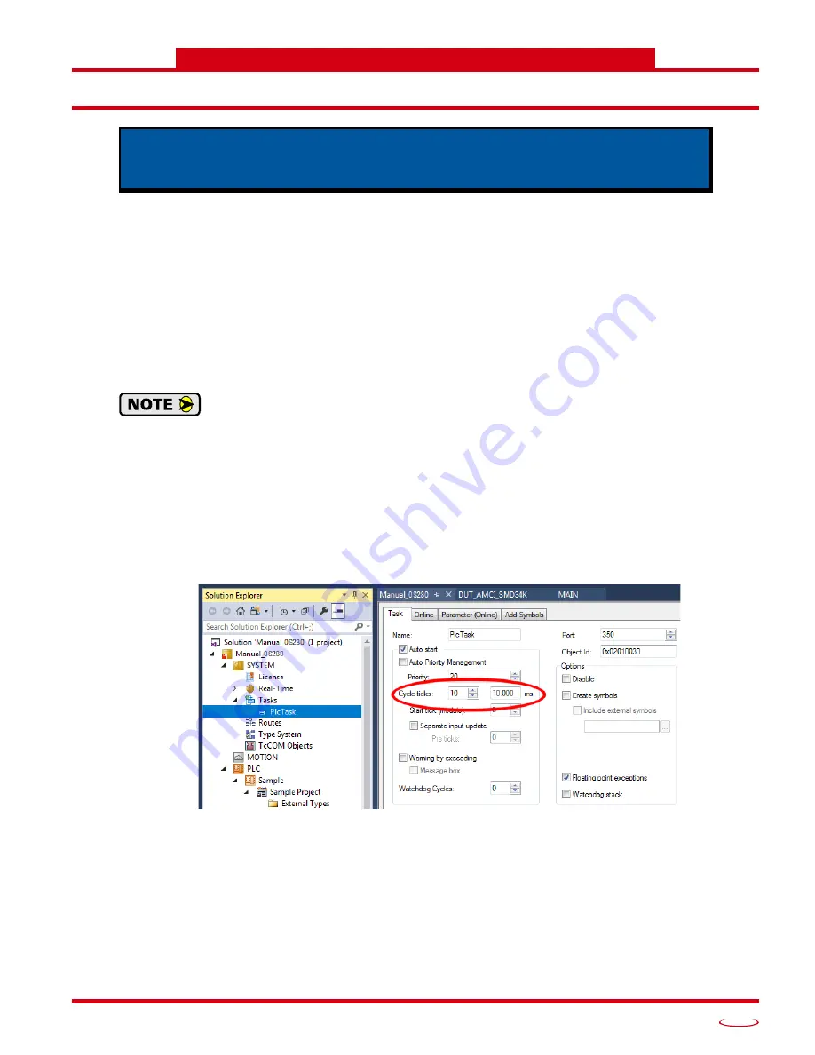
3.1 Verify Main PLC Task Timing
1) In the
Solutions Explorer
, expand out
System
Tasks
so that the tasks are visible. Double click on the task
assigned to the main PLC. This task is typically named
PlcTask
. In the windows that open, note the value
for Cycle Ticks and its time in milliseconds. These values are typically 10 ticks and 10.000 milliseconds.
You can change the timing of the main task here, but this will affect the timing of every program that
runs under this task.
Figure T3.1 Main PLC Task Timing
2) If this value is between 2 and 50 milliseconds and the correct update time for the SMD34K, skip to step
3.3. When setting the
SYNC 0 -> Sync Unit Cycle
multiplier in step 6 of 3.3, use a value of 1.
3) If the timing in step 1 above is not correct for the SMD34K, but the correct time is an integer multiple of
this timing, then skip to step 3.3. When setting the
SYNC 0 -> Sync Unit Cycle
multiplier in step 6 of 3.3,
use the correct integer multiplier.
4) If the timing is step 1 above is not correct for the SMD34K, and the correct time is
not
an integer multiple
of this timing, then proceed with step 3.2.
This chapter outlines the steps need to configure the SMD34K to synchronize to
the Sync0 signal from the Distributed Clock (DC) feature instead of the SyncMan-
ager 2 event. This configuration is optional.
Содержание SMD34K
Страница 1: ...MICRO CONTROLS INC ADVANCED U s e r M anual Manual 940 0S280 ...
Страница 6: ...TABLE OF CONTENTS SMD34K User Manual ADVANCED MICRO CONTROLS INC 6 Notes ...
Страница 50: ...CALCULATING MOVE PROFILES SMD34K User Manual ADVANCED MICRO CONTROLS INC 50 Notes ...
Страница 62: ...CONFIGURATION DATA FORMAT SMD34K User Manual ADVANCED MICRO CONTROLS INC 62 Notes ...
Страница 80: ...COMMAND DATA FORMAT SMD34K User Manual ADVANCED MICRO CONTROLS INC 80 Notes ...
Страница 100: ...LEADERS IN ADVANCED CONTROL PRODUCTS ADVANCED MICRO CONTROLS INC ...


