Amazone UX 3200 Special Скачать руководство пользователя страница 18


General safety instructions 


2.13 

Warning symbols and other signs on the machine 


Always keep all the warning symbols on the machine clean and in a 
legible state. Replace illegible warning symbols. You can obtain the 
warning symbols from your dealer using the order number (e.g. MD 
075).  

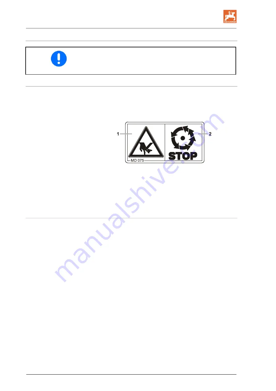
Warning symbols - structure 


Warning symbols indicate danger areas on the machine and warn 
against residual dangers. At these points, there are permanent or 
unexpected dangers. 

A warning symbol consists of two fields: 


Field 1 

is a symbol describing the danger, surrounded by triangular safety 
symbol. 

Field 2 

is a symbol showing how to avoid the danger. 

Warning symbols - explanation 


The column 

Order number and explanation 

provides an explanation 

of the neighbouring warning symbol. The description of the warning 
symbols is always the same and specifies, in the following order: 

  1.  A description of the danger. 


  For example: risk of cutting 

  2.  The consequence of non-compliance with the risk avoidance 

instructions. 


  For example: causes serious injuries to fingers or hands. 

  3.  Risk avoidance instructions. 


  For example: only touch machine parts when they have come to 

a complete standstill. 

18  

UX Super

 BAG0054.10  11.16 


Содержание UX 3200 Special

Страница 1: ...UX 3200 Super UX 4200 Super UX 5200 Super UX 6200 Super Trailed field sprayer MG3403 BAG0054 10 11 16 Printed in Germany Please read this operating manual before commissioning Keep it in a safe place...

Страница 2: ...n would not only harm himself but also make the mistake of blaming the machine for pos sible failures instead of himself In order to en sure success one should enter the mind of a thing make himself f...

Страница 3: ...GmbH Co KG Postfach 51 D 49202 Tel E mail Hasbergen Germany 49 0 5405 501 0 amazone amazone de Spare part orders Spare parts lists are freely accessible in the spare parts portal at www amazone de Pl...

Страница 4: ...fety information Only after careful reading will you be able to benefit from the full scope of your newly purchased machine Please ensure that all the machine operators have read this operating manual...

Страница 5: ...eneral safety and accident prevention information 29 2 16 2 Hydraulic system 32 2 16 3 Electrical system 33 2 16 4 Universal joint shaft operation 34 2 16 5 Coupled machines 35 2 16 6 Brake system 35...

Страница 6: ...ar 81 5 11 2 AutoTrail steering axle 82 5 12 Tracking control via tractor control unit 83 5 13 Hydraulic stand 84 5 14 Mechanic stand 84 5 15 Spray liquid tank 85 5 15 1 Fill level indicator on the ma...

Страница 7: ...ray nozzles optional 125 6 12 2 7 hole nozzles FD nozzles optional 126 6 12 3 Drag hose equipment for Super S boom optional 127 6 12 4 Drag hose equipment for Super L boom optional 128 6 13 Foam mark...

Страница 8: ...ical agent change 184 10 5 9 Cleaning the sprayer with a full tank work interruption 185 11 Faults 186 12 Cleaning maintenance and repair 187 12 1 Cleaning 189 12 2 Winter storage and long periods out...

Страница 9: ...ghtening torques 227 12 21 Disposing of the field sprayer 228 13 Spray table 229 13 1 Spray tables for flat fan anti drift injector and airmix nozzles spraying height 50 cm 229 13 2 Spraying nozzles f...

Страница 10: ...directions specified in the operating manual are always seen in the direction of travel 1 3 Diagrams Instructions and responses Activities to be carried out by the user are given as numbered instruc t...

Страница 11: ...in working with on the machine have read and understood this operating manual The operator is obliged to keep all the warning symbols on the machine in a legible state to replace damaged warning symb...

Страница 12: ...he operator at the latest on conclusion of the contract Guarantee and liability claims for damage to people or property will be excluded if they can be traced back to one or more of the following caus...

Страница 13: ...y WARNING Indicates a medium risk which could result in death or serious physical injury if not avoided If the instructions are not followed then this may result in death or serious physical injury CA...

Страница 14: ...maintenance personnel Check all safety equipment regularly 2 4 Safety and protection equipment Before starting up the machine each time all the safety and protection equipment must be properly attach...

Страница 15: ...ained if necessary and have been in formed about the necessary protective equipment and measures 3 People with specialist technical training shall be considered as a specialist Due to their specialist...

Страница 16: ...devices 2 10 Design changes You may make no changes expansions or modifications to the ma chine without the authorisation of AMAZONEN WERKE This also applies when welding support parts Any expansion o...

Страница 17: ...d parties does not guarantee that they have been constructed in a way as to meet the requirements placed on them AMAZONEN WERKE shall accept no liability for damage caused by the use of non approved s...

Страница 18: ...lds Field 1 is a symbol describing the danger surrounded by triangular safety symbol Field 2 is a symbol showing how to avoid the danger Warning symbols explanation The column Order number and explana...

Страница 19: ...fety instructions 2 13 1 Positions of warning symbols and other labels Warning symbols The following diagrams show the arrangement of the warning symbols on the machine Fig 1 Fig 2 UX Super BAG0054 10...

Страница 20: ...General safety instructions Fig 3 Fig 4 20 UX Super BAG0054 10 11 16...

Страница 21: ...moving MD 078 Risk of crushing fingers or hands by acces sible moving machine parts This danger causes serious injuries including loss of body parts such as fingers or hand Never reach into the danger...

Страница 22: ...4 Risk of electric shock or burns from accidental ly touching overhead power lines or by coming within the prohibited distance of high voltage overhead power lines This danger causes serious or potent...

Страница 23: ...rrying out maintenance work on the hydraulic hose lines If you are injured by hydraulic fluid contact a doctor immediately MD 099 Risk of contact with hazardous materials due to improper handling This...

Страница 24: ...achine parts These dangers can cause extremely serious and potentially fatal injuries Maintain an adequate safety distance from moving machine parts while the tractor en gine is running Please ensure...

Страница 25: ...y fill the hand wash tank with clear fresh wa ter and never with crop protection agent MD 172 Swing the ladder to the operation platform up wards into transport position when driving MD 173 Risk of br...

Страница 26: ...10 Nm MD 192 Danger of fluids escaping under high pres sure while working on hoses and connec tions under pressure This can result in extremely serious injuries on all parts of the body It is not allo...

Страница 27: ...while the tractor engine is running and the tractor is not secured against unintentional rolling Instruct anyone in the danger area between tractor and machine to leave the danger ar ea while the tra...

Страница 28: ...nger to people through non secured working areas Failure of important machine functions Failure of prescribed methods of maintenance and repair Danger to people through mechanical and chemical influen...

Страница 29: ...isibility and weather conditions the driving characteristics of the tractor and the connected machine Coupling and uncoupling the machine Only connect and transport the machine with tractors suitable...

Страница 30: ...tand all the equip ment and actuation elements of the machine and their function There is no time for this when the machine is already in opera tion Do not wear loose fitting clothing Loose clothing i...

Страница 31: ...ination tractor plus connected machine Check the brake power before moving off When turning corners with the machine connected take the broad load and balance weight of the machine into account If the...

Страница 32: ...cked at least once a year by a specialist for proper functioning Replace the hydraulic hose lines if they are damaged or worn Only use original AMAZONE hydraulic hose lines The hydraulic hose lines sh...

Страница 33: ...accidental earth contact there is a risk of ex plosion Risk of explosion Avoid sparking and naked flames in the area of the battery The machine may be equipped with electronic components whose functio...

Страница 34: ...shaft manufacturer When turning corners observe the permitted bending and dis placement of the PTO shaft Before switching on the universal joint shaft check that the se lected universal joint shaft sp...

Страница 35: ...e driving behaviour and steering and braking power of the tractor and in particular single axle machines with drawbar loads on the tractor Only one specialist workshop can adjust the height of the dra...

Страница 36: ...ioning belts the air reservoir is damaged the rating plate on the air reservoir is rusty loose or miss ing Hydraulic brake system for export machines Hydraulic brake systems are prohibited in Germany...

Страница 37: ...d tank must not be ex ceeded during filling When there will be exposure to crop protection agent wear the proper protective clothing i e gloves overalls safety glasses etc When using tractors with a c...

Страница 38: ...e to the tractor generator and battery before carrying out electrical welding work on the tractor and on at tached machines Spare parts must meet at least the specified technical require ments of AMAZ...

Страница 39: ...y power requirements Pneumatic braking system Only move off with the machine connected when the pressure gauge on the tractor shows 5 0 bar Loading using a lifting crane There are 4 attachment points...

Страница 40: ...better 4 1 Overview of the assemblies Fig 7 1 Spray liquid tank 2 Filling opening for spray liquid tank 3 Pressure gauge 4 Swivel out induction bowl in filling position 5 Flushing water tank 1 6 Flus...

Страница 41: ...ter tank 2 2 Flushing water tank 2 filling opening 3 Hydraulic stand 4 Parking brake 5 Pump equipment 6 Wheel chocks 7 Hydraulic block with system setting screw job computer 8 Oil filter with clogging...

Страница 42: ...ort locking mechanism Fig 10 to prevent the Super S boom from folding out unintentionally Fig 10 Fig 11 Handrail on the Maintenance platform Fig 11 Fig 12 1 PTO shaft guard with supporting chains 2 Ma...

Страница 43: ...ol valve 17 Pressure filter 18 Fill level gauge 19 Quick emptying via pump 20 Flow rate sensor 21 Part width section valve 22 DUS pressure circulating system 23 Spray lines 24 Injector 25 Machine comp...

Страница 44: ...e Fig 15 4 5 Transportation equipment Fig 16 1 Rear lights brake lights turn indicators 2 2 warning signs square 3 2 red reflectors triangular 4 1 registration plate holder with lighting Fig 16 Fig 17...

Страница 45: ...ntrol for precise tracking is prohibited if on sloping terrain See page 72 Restrictions for use on slopes 1 Driving on slopes with a full spray liquid tank 2 Driving on slopes with a partially full sp...

Страница 46: ...ancolan and Ter idox can cause damage to the pump diaphragms hoses spray lines and tanks The examples given are in no way intended to represent a comprehensive list In particular we warn against unaut...

Страница 47: ...may stand in the machine danger area if the tractor engine is running with the PTO shaft hydraulic system connected if the tractor and machine are not protected against unintentional start up and rol...

Страница 48: ...ible support load kg Permissible rear axle load kg Permissible system pressure bar Permissible total weight kg Factory Model year Year of manufacture Fig 20 4 11 Conformity Directives Standards design...

Страница 49: ...min The agitator capacity per minute must be 5 of the hopper volume Permissible application rate Pump capacity 0 05 x nominal tank volume l min l min l See page 93 See page 51 Conversion of the appli...

Страница 50: ...00 6200 6250 6500 6850 7300 UX 3200 4200 5200 3250 3400 UX 6200 3650 4 13 2 Total UX measurements including Super L sprayer boom mm UX 3200 4200 5200 UX 6200 2400 2600 2800 UX 3200 UX 4200 5200 6200 6...

Страница 51: ...king speed km h 4 18 Working width m 18 36 18 40 18 40 18 40 Central switching mechanism Electric part width section valve coupling Spray pressure adjustment Electric Spray pressure setting range bar...

Страница 52: ...suspension 585 Axle controlled with hydropneumatic sprung suspension 798 Drawbar Straight drawbar fixed 108 Straight drawbar controlled 150 Hitch draw bar fixed 113 Hitch draw bar controlled 145 Hitch...

Страница 53: ...weight and tyres The permissible total weight of the machine depends on the permitted drawbar load permitted axle load permitted load capacity per pair of tyres The permissible total weight is the tot...

Страница 54: ...0 1500 2250 1500 1750 1800 2250 1800 2250 1800 2250 2000 2250 2000 2250 Axle load kg 25 km h 3000 1 7500 7500 9500 9500 9500 11500 11500 max 6000 2 Axle load kg 40 km h 50 km h 6500 6500 7500 8000 800...

Страница 55: ...000 1 6 5450 1 6 6 480 80 R42 LI 148 A8 LI 145 B 6990 1 6 6300 1 6 5800 1 6 7 520 85 R38 LI 155 A8 LI 152 B 8600 1 6 7750 1 6 7100 1 6 8 520 85 R42 LI 155 A8 LI 152 B 8600 1 6 7750 1 6 7100 1 6 9 520...

Страница 56: ...12 table 1 Air pressure b 1 6 1 8 2 1 2 4 max load capacity 79 86 93 100 Tyres 13 table 1 Air pressure b 1 0 1 3 1 7 2 1 max load capacity 65 76 88 100 Tyres 14 16 table 1 Air pressure b 1 0 1 2 1 4 1...

Страница 57: ...150 bar for hydraulic pump drive optional Implement hydraulic fluid HLP68 DIN 51524 The implement hydraulic fluid is suitable for the combined hydraulic fluid circuits of all standard tractor brands...

Страница 58: ...tion valves then send the liquid to separate spray lines Via the additional agitator setting tap I on the pressure filter the stirring performance can be increased when stirring spray liquid to the in...

Страница 59: ...quid outlet 8 Pressure filling connection optional 9 Button for comfort equipment optional A Pressure equipment switch tap B Internal cleaning switch tap C External cleaning switch tap D Injector swit...

Страница 60: ...aning switch tap D Injector switch tap Optional L Filling switch tap M Quick emptying switch tap Fig 23 E Ring line canister flushing switch tap 0 Zero setting Ring line Canister flushing Fig 24 F Eva...

Страница 61: ...the suction chest manually there may be a squeaking noise This noise does not signify any danger Fig 26 H Main agitator switch tap Fig 27 I Additional agitator switch tap Release residue in the press...

Страница 62: ...use the PTO shaft if the safety device is missing or dam aged or without correctly using the supporting chain Before each use check that all PTO shaft protective devices are installed and fully func t...

Страница 63: ...the operating manual provided for the PTO shaft Correct use and maintenance of the PTO shaft prevents serious accidents When coupling the PTO shaft refer to the operating manual provided for the PTO s...

Страница 64: ...t over the universal joint shaft of the tractor until the latch is heard to engage When coupling the PTO shaft refer to the operating manual provided for the PTO shaft and observe the permissible univ...

Страница 65: ...supporting chain on the PTO shaft to hang up the uncoupled PTO shaft Clean and lubricate the PTO shaft if it is going to be out of use for a long time 1 Uncouple the machine from the tractor Refer to...

Страница 66: ...activa tion depending on the hydraulic function Latched for a permanent oil circulation Tentative activate until the action is executed Float position free oil flow in the control unit Folding using...

Страница 67: ...immediately Profi folding Maximum permissible pressure in oil return 5 bar Therefore do not connect the oil return to the tractor control unit but to a pressure free oil return flow with a large plug...

Страница 68: ...draulic sockets until you can feel the hydraulic plug s locking Check the coupling points on the hydraulic hose lines to see if they are sitting correctly and are sealed 1 Swivel the actuation lever o...

Страница 69: ...ll load Sprayer partly filled Sprayer empty empty 2 Release valve with actuator button 3 3 Actuator button press in until it stops and the service brake system releases e g for shunt ing the uncoupled...

Страница 70: ...braking force is regulated according to the tank fill level via a float in the tank WARNING Risk of crushing cutting being caught or drawn in or impact through incorrectly functioning brake system You...

Страница 71: ...g system Always couple the hose coupling on the brake line yellow first and then the hose coupling on the supply line red The service brake on the machine is immediately released from the brake settin...

Страница 72: ...e system will trip and may set the unbraked machine moving When the machine is uncoupled or pulled away from the trailer air is vented from the trailer brake valve supply line The trailer brake valve...

Страница 73: ...ulic screw union if present hand tight 5 6 2 Uncoupling the hydraulic service brake system 1 Loosen the hydraulic screw union if present 2 Protect the hydraulic plug and hydraulic socket against soili...

Страница 74: ...ng the emergen cy brake it is essential to insert the safety splint into the brake valve from the same side Fig 35 Otherwise the brake will not function After reinserting the safety splint carry out a...

Страница 75: ...position for releasing applying in the end area the parking brake requires approx 20 kg manual force to be applied Fig 37 Crank position for quick releasing apply ing A Apply the tractor parking brak...

Страница 76: ...hocks Each of the wheel chocks is attached with a thumb bolt on the right side of the implement Fig 39 Put the foldable wheel chocks into operating posi tion by pressing the button and apply directly...

Страница 77: ...system Implements without a brake system or with a single line brake system must be equipped with a safety chain in compliance with local country regulations The safety chain must be correctly fixed t...

Страница 78: ...fastened in the tractor pin coupling Fig 42 Hitch drawbar Fig 43 The hitch drawbar is fastened in the tractor hitch hook Fig 43 Draw bar for UniTrail steering system The machine is coupled to the tra...

Страница 79: ...on of travel cable to rear and secure with a locking screw against rotation See operating manual for software ISOBUS A precondition for the perfect functioning of the hydraulically operated following...

Страница 80: ...teering axle to the central position steering drawbar wheels in line with machine On the control terminal for this purpose 1 1 Put AutoTrail in manual operation 1 2 Move to the centre position 1 3 Mov...

Страница 81: ...tracking steering drawbar there is a risk of tipping over when performing a turning manoeuvre on a headland and on tight bends at high speeds due to the shifting of the centre of gravity when the stee...

Страница 82: ...widths greater than 500 mm 1 Turn the steering axis as far as it will go via the manual control on the control terminal so that colli sions do not occur 2 Tighten the locking screw Fig 48 1 in the bra...

Страница 83: ...y hydraulic control reduces damage to the crop particularly with regard to drill crops e g potatoes or vegeta bles when driving or manoeuvring in and out of the drills Turning circle dwk 18 m Transpor...

Страница 84: ...mark Fig 51 1 on the stand control display is visible if the machine is resting on the hy draulic stand 5 14 Mechanic stand UX with steering drawbar Risk of collision between the raised stand and Mai...

Страница 85: ...id for filling opening 4 External filling connection 5 Filling sieve 6 Ventilation 7 Float for determining the fill level 8 Agitator 9 Additional agitator When using the machine parts of the framework...

Страница 86: ...ure filter The main agitator has its own agitator pump The additional agitator is supplied by the operation pump When the agitators are switched on they mix the spray liquid in the spray liquid tank t...

Страница 87: ...jury from poisonous vapours Never climb into the spray liquid tank Riding on the machine creates a risk of falling Riding on the field sprayer is prohibited You MUST ensure that the ladder is locked i...

Страница 88: ...om running out if the vacuum suddenly collapses during the filling process Fig 58 5 15 5 Filling connection for filling the spray liquid tank with pressure option Filling with free flow path and swive...

Страница 89: ...he residue in the spray liquid tank at the end of spraying operation clean flush the whole field sprayer in the field clean the suction chest and the spray lines when the tank is full Only fill the fl...

Страница 90: ...el the induction bowl in filling position 1 Take hold of the handle on the induction bowl 2 Unlock transport safety catch Fig 64 1 3 Swivel the induction bowl down Fig 65 1 The bottom sieve in the ind...

Страница 91: ...against unin tentional spraying using the locking mechanism Fig 67 1 before each pause in spraying before depositing the spray gun in its holder after cleaning work is complete 5 18 Filling connectio...

Страница 92: ...agent or spray liquid Always fill the clear water tank with clear freshwater only and never with crop protection agent or spray liquid When using the field sprayer make sure that there is always an ad...

Страница 93: ...280 Delivery capacity at nominal speed l min at 0 bar 160 260 2 x 260 at 10 bar 155 245 2 x 245 Power requirement kW 4 6 6 9 2 x 6 9 Construction type 4 cylinder piston dia phragm pump 6 cylinder pist...

Страница 94: ...er and the nozzle filters must always be smaller than the nozzle opening of the nozzles in question Ensure that the use of pressure filter inserts with 80 or 100 mesh inch for some crop protection age...

Страница 95: ...ure filter inserts 50 mesh inch standard blue for nozzle size 03 and larger Filter area 216 mm Mesh size 0 35 mm 80 mesh inch yellow for nozzle size 02 Filter area 216 mm Mesh size 0 20 mm 100 mesh in...

Страница 96: ...e total weight of 8000 kg and overrun brake with a total weight which is lower than the permitted total weight of the field sprayer without drawbar load with towing eye 40 DIN 74054 Fig 77 1 Drawbar 2...

Страница 97: ...pproach the trailer Coupling the trailer via the automatic drawbar is a one man operation Helpers as guides are not necessary WARNING When coupling and uncoupling trailers follow the safety instruc ti...

Страница 98: ...pressure 10 bar Water output 18 l min Fig 80 Fig 81 WARNING Danger from liquids escaping under pressure and contamination with spray liquid if the spray gun is acti vated accidentally Secure the spray...

Страница 99: ...tional The implement can be equipped with Fig 82 1 and Fig 83 1 a cam era Features Viewing angle of 135 Heater and lotus coating Infrared night view technology Automatic backlight compensation Super S...

Страница 100: ...loodlights on the sprayer boom and 2 work floodlights on the platform Fig 84 LED individual nozzle illumination Fig 85 2 variants Separate power supply from the tractor is required operation via the d...

Страница 101: ...ic fill level dependent regula tion of the main agitator agitator tap missing from control terminal Automatic agitator cut off if fill level drops below 200 litres Manual setting of the agitating inte...

Страница 102: ...uter receives all necessary information and manages the area based regula tion of the spray rate l ha depending on the quantity target quantity entered and the current operational speed km h Fig 87 Se...

Страница 103: ...boom extension Profi folding II only Folding via the tractor control unit The boom is operated via tractor control units Depending on equipment sprayer boom folding must be select ed using the control...

Страница 104: ...is running Ensure that all personnel maintain an adequate safety distance from moving machine parts Instruct personnel to leave the swivel range of any moving machine parts before swivelling the part...

Страница 105: ...e swing compensation Even lateral distribution can only be achieved with the swing compen sation unlocked After the sprayer boom is fully folded out actuate the operating lever for another 5 seconds T...

Страница 106: ...amage if the outer boom sections come into contact with solid obstructions The locking mechanism enables the outer boom sec tion to avoid collision by moving around the ar ticulated axle in and agains...

Страница 107: ...Boom equipment 7 Pressure sensor Fig 92 1 Pressure connection for the spraying pressure pressure gauge 2 Flow meter for determining the spray rate l ha 3 Return flow meter for determining the spray l...

Страница 108: ...stment until the catching lugs Fig 93 1 are released from the catching sockets Fig 93 2 The transport safety catch unlocks the sprayer boom from the transport position Fig 93 shows the unlocked spraye...

Страница 109: ...down the individual segments are fully folded out and the swing compensation is unlocked The appropriate hydraulic cylinders lock the boom in its working position Folding out does not always happen s...

Страница 110: ...tion see page 105 8 Valve and switch tap for DUS system 9 Boom equipment see Fig 96 Fig 96 1 Pressure connection for the spraying pressure pressure gauge 2 Flow meter for determining the spray rate l...

Страница 111: ...ety catch before undertaking road transport The transport safety bows are for securing the folded sprayer boom against accidental unfolding while in transport position Unlocking the transport safety c...

Страница 112: ...re folded back the individual segments are fully unfolded and the swing compensation is unlocked The appropriate hydraulic cylinders lock the boom in its working position Folding out does not always h...

Страница 113: ...n locked Unless the sprayer boom is guided smoothly even lateral distribution cannot be guaranteed The sprayer boom is fully unfolded 1 Lock the swing compensation 2 Using the height adjustment lift t...

Страница 114: ...h sections switched off Case 2 Number of nozzles outer part width section Number of nozzles on the foldable outer element Close the outer nozzles manually triple nozzle head Perform changes on the con...

Страница 115: ...ted in the on board computer Fig 99 1 Boom width reduction 2 Boom width damping option A Stop tap opened B Stop tap closed Working with reduced working width 1 Reduce the boom width hydraulically 2 Cl...

Страница 116: ...nsor Fig 100 6 6 Boom extension option The boom extension increases the working width infinitely up to 1 20 metres Fig 101 1 Boom extension in transport position 2 Boom extension in working position 3...

Страница 117: ...boom parallel at the desired distance from the target surface DistanceControl with 2 sensors DistanceControl with 4 sensors Ultrasound sensors Fig 102 1 detect the dis tance to the ground or the crop...

Страница 118: ...chnical data Ensure that the residue in the spray line is still being sprayed at an undiluted concentration Always spray this residue on an untreated area The residue contained in the spray line is de...

Страница 119: ...0 18 0 7 6 6 6 6 6 6 6 5 0 10 0 15 0 16 0 1 5 17 5 20 0 9 4 4 6 5 4 5 6 4 4 5 0 11 0 16 0 17 0 1 5 18 5 22 0 11 4 4 3 3 5 4 5 3 3 4 4 5 5 15 5 21 0 17 5 1 5 19 0 24 0 21 15 7 6 6 6 6 6 6 6 5 0 10 0 1...

Страница 120: ...5 4 4 5 4 5 4 4 5 4 4 6 0 25 5 31 5 33 5 2 5 36 0 28 0 30 9 8 7 6 6 6 6 6 7 8 5 5 18 0 23 5 24 0 2 5 26 5 32 0 11 5 5 5 6 6 6 6 6 5 5 5 6 0 22 5 28 5 29 0 2 5 31 5 39 0 13 3 3 4 5 5 7 6 7 5 5 4 3 3 6...

Страница 121: ...s with 50 mesh inch is inserted from below into the nozzle body Refer to the Nozzle filter section 7 Rubber seal 8 Nozzle 9 Bayonet connection 10 Coloured bayonet cap 11 Spring element housing Fig 104...

Страница 122: ...aphragm seat 5 in the three way nozzle carrier This ensures that when the sprayer boom is switched off the nozzles are deac tivated without subsequent dripping 4 Spring element 5 Diaphragm seat 6 Slee...

Страница 123: ...at the edge of the field Fig 107 6 9 5 Electric end nozzle switching optional Using end nozzle switching up to three of the outer nozzles at the edge of the field close to a water source can be elect...

Страница 124: ...width section control Section Control overlapping can be reduced to a minimum area 6 11 1 Single nozzle control AmaSwitch Each nozzle can be switched on and off separately via Section Con trol 6 11 2...

Страница 125: ...version table for spraying liquid fertiliser Always dis continue nozzle based AUS fertilisation at development stage EC 39 because chemical burns on ears have a particularly bad effect 6 12 1 Three ra...

Страница 126: ...This allows very large drops to be produced on the plants using only slight impact forces Fig 111 7 hole nozzle Fig 112 FD nozzle Fig 111 Fig 112 The following 7 hole nozzles are available SJ7 02 CE 7...

Страница 127: ...ion of travel no 2 next to it and so on 2 Thumb nuts for securing the drag hose unit 3 Turned plug connection for connecting the hoses 4 Metal weights stabilise the position of the hoses during opera...

Страница 128: ...sport hook 3 Spacing runners Remove both spacing runners Fig 115 3 when operating drag hoses Fig 116 1 one setting tap for every boom part width section a Spraying via both spray lines with drag hoses...

Страница 129: ...metres providing a clearly visible orientation line The foam bubbles dis solve after a certain time without leaving any residue behind Set the interval between the individual appli cations of bubbles...

Страница 130: ...perating device For implements without control terminal Fig 121 1 Left hand foam marker on 2 Right hand foam marker on 3 Foam marker off 4 Connection to the compressor 5 Connection to the tractor powe...

Страница 131: ...pray pattern right from the start because spray liquid is available at every spraying nozzle immedi ately after the sprayer boom is switched on with no delay prevents damage to the spray line Fig 122...

Страница 132: ...and function of the sprayer boom Overview pressure circulating system DUS Fig 124 1 Pressure circulating system DUS 2 DUS switch tap 3 DUS pressure limiting valve 4 DUS return valve 132 UX Super BAG0...

Страница 133: ...of damaging the machine When driving on the roads the sprayer boom must not be raised above the lifting module The total height of the machine with lifting module can be con siderably higher than 4 m...

Страница 134: ...nd machine must meet the national road traffic regulations The operator and the user shall be responsible for compliance with the statutory road traffic regulations WARNING Risk of crushing shearing c...

Страница 135: ...ead weight of the tractor The tractor must achieve the brake rate specified by the tractor manu facturer even with the machine connected 7 1 1 Calculating the actual values for the total tractor weigh...

Страница 136: ...tractor and front ma chine mounting or front ballast or measure ment a1 m Distance from the centre of the front axle to the centre of the lower link connection See tractor operating manual or measure...

Страница 137: ...n the table Section 7 1 1 7 7 1 1 4 Calculation of the actual total weight of the combined tractor and machine H L V tat F T G G Enter the numeric value for the calculated actual total weight and the...

Страница 138: ...calculated values must be less than or equal to the permissible values WARNING Risk of crushing cutting being caught or drawn in or impact through insufficient stability and insufficient tractor steer...

Страница 139: ...tted drawbar load You will find the maximum permitted drawbar load in the vehicle doc umentation or on the rating plate on the connection fitting of your trac tor Maximum permissible drawbar load Conn...

Страница 140: ...on the connection fitting itself in the operating manual for your tractor 7 1 3 Machines without their own brake system WARNING Risk of crushing cutting being caught or drawn in or impact through inad...

Страница 141: ...ractor type You may need to readjust the PTO shaft if you couple the ma chine to another tractor WARNING Risk of being caught and drawn in if the PTO shaft is installed incorrectly or if unauthorised...

Страница 142: ...raise and lower the machine via the tractor s three point hydraulic system While doing so actuate the manual controls for the tractor s three point hydraulic system on the rear of the tractor from th...

Страница 143: ...actor engine is running with a connect ed PTO shaft hydraulic system when the ignition key is inserted in the tractor and the trac tor engine with the connected PTO shaft hydraulic system could be sta...

Страница 144: ...on page 39 2 Loosen wheel nuts on the inflatable spare tyres 3 Remove inflatable spare tyres CAUTION Take care when removing the inflatable spare tyres and putting the running wheels in place 4 Place...

Страница 145: ...rew caused by persistent strain on the pressure relief valve of the tractor hydraulic system Adjustments may only be made in a pressureless state If there are hydraulic malfunctions between the tracto...

Страница 146: ...ressure and flow regulated setting pump with direct load sensing pump connection and LS set ting pump Put the system setting screw in position B 3 Load Sensing hydraulic system with con stant flow pum...

Страница 147: ...ovided When installed the position encoder must be directly above the pivot point of the tractor pin coupling Fig 131 4 Keep the distance between the coupling point and position encoder Fig 132 X as s...

Страница 148: ...h mm 740 mm 2 Perform the track width adjustment as follows 1 Hang the sprayer on the tractor 2 Secure the tractor implement against unin tentional starting and rolling away 3 Lift the sprayer on one...

Страница 149: ...ols for the tractor s three point linkage from the intended workstation if you are outside of the danger area between the tractor and the machine 8 1 Coupling the machine WARNING Risk of breaking duri...

Страница 150: ...wer link hooks are correctly locked before reversing the tractor WARNING Risk of energy supply failure between the tractor and the ma chine due to damaged power supply lines During coupling check the...

Страница 151: ...ine from the tractor 2 1 Secure the machine against unintentionally rolling See page 143 2 1 Lower the stand to the parking position 2 2 Uncouple the connection fitting 2 3 Draw the tractor forwards b...

Страница 152: ...e air reservoir Remove all air from the braking system at the drain valve on the air reservoir 1 Connect the machine to the manoeuvring vehicle 2 Brake the manoeuvring vehicle 3 Remove the wheel chock...

Страница 153: ...e machine against unintentional movements before starting transportation WARNING Risk of crushing cutting being caught and or drawn in or im pact from tipping and insufficient stability Drive in such...

Страница 154: ...cure mechanically If a working width reduction of the outer elements is mounted unfold it for transporting purposes Use the transport safety catch to secure the induction bowl when it has been swivell...

Страница 155: ...that you always have full control over the tractor whether the machine is attached or unattached In so doing take your personal abilities into account as well as the road traffic visibility and weathe...

Страница 156: ...ea of the driven PTO shaft Shut down the tractor engine immediately in case of danger WARNING Risk of accidental contact with crop protection agents spray liquid Wear personal protective equipment whe...

Страница 157: ...lic cylinder 10 1 Preparing for spraying operation The field sprayer must be operating properly in order to guaran tee correct application of the crop protection agent Have the field sprayer tested re...

Страница 158: ...n agents and or spray liquids by taking proper care and by wearing the appropriate physical protection equipment To avert risks to third parties do not leave any prepared spray liquid unused crop prot...

Страница 159: ...r Pay attention to the respec tive specific weight of the liquid in question While filling keep watch on the fill level indicator to avoid overfilling the spray liquid tank While filling the spray liq...

Страница 160: ...ill the machine and blend in the agent 4 Agitate the spray liquid before commencing spraying operations in accordance with the instructions of the spraying agent manu facturer Fill the machine prefera...

Страница 161: ...f them in a proper manner Do not re use them for other purposes If only spray liquid is available for washing the agent canisters first use this to carry out preliminary cleaning Then wash them meticu...

Страница 162: ...Agent B must be used to treat a surface of 2 5 ha in area Answer Water 400 l ha x 2 5 ha 1000 l Agent A 1 5 kg ha x 2 5 ha 3 75 kg Agent B 1 0 l ha x 2 5 ha 2 5 l Example 2 The following are given fa...

Страница 163: ...ance Working width m 15 16 18 20 21 24 27 28 30 32 33 36 39 40 m Refill quantity l 10 2 2 2 2 2 2 3 3 3 3 3 4 4 4 20 3 3 4 4 4 5 5 6 6 6 7 7 8 8 30 5 5 5 6 6 7 8 8 9 10 10 11 11 12 40 6 7 7 8 8 10 11...

Страница 164: ...elevation source 1 Connect the suction hose to the filling con nection and water access point 2 Move suction chest lever G to position 3 Move the pressure gauge switch tap A to position 4 Open switch...

Страница 165: ...g in the agent the supply of water and the suction speed can be adjusted using switch taps E and F 14 Pour the quantity of agent calculated and measured for filling the tank into the induc tion bowl T...

Страница 166: ...gitator H again to a medium position Fig 138 Increasing the suction power by cutting in the injector Move switch tap F to position The injector must not be cut in until the pump has drawn in water The...

Страница 167: ...on 0 6 Move switch tap O to position 1 Evacuate the ECO Fill container 7 Move switch tap O to position 0 when the desired quantity has been evacuated from the ECO Fill container Fig 139 Rinsing the EC...

Страница 168: ...position Where necessary increase the agitating power for a more effective mixing 5 Manually move suction chest G to position 6 Move the pressure gauge switch tap A to position 7 Open switch tap D 8 O...

Страница 169: ...16 Press the canister down for at least 30 secs The canister is washed with flushing water If spray liquid was previously being used it takes a little time before the flushing water reaches the nozzle...

Страница 170: ...tap N to position 0 when reach ing 80 of the filling level at the latest This allows you to clean the can ister with no hurry Complete filling the spray liquid tank 24 Move switch tap N to position 0...

Страница 171: ...required nozzle type from the spray table before start ing to spray taking into account the prescribed operational speed the required spray rate and the required atomisation characteristic fine medium...

Страница 172: ...ee Control terminal AMASPRAY operating manual If spraying operations must be interrupted because of bad weather by all means clean the suction filter the pump the valve chest and the spray lines See p...

Страница 173: ...e spray liquid Properly couple the field sprayer to the tractor Before starting to spray check the following machine data on the control terminal the values for the permitted spray pressure range of t...

Страница 174: ...urer 2 Manually move suction chest G to posi tion 3 Move the pressure gauge switch tap A to position 4 Switch on agitator H I The agitator power can be set variably 5 Switch on the control terminal 6...

Страница 175: ...between the nozzles increases Reduce operational speed to below 8 km h Use so called anti drift AD nozzles or injector ID nozzles nozzles which produce a high proportion of coarse drops Observe the d...

Страница 176: ...eaned with air dis charge from the nozzles This final diluted residue is drained off after cleaning Disposing of the residues Make sure that the residue in the spray line continues to be sprayed in an...

Страница 177: ...ater supply using agitator H 5 Once the desired filling level has been reached Manually move suction chest G to position 6 Move agitator H I to position 0 7 Switch on the sprayers on the on board comp...

Страница 178: ...ge hose to the drainage connection on the machine side using a 2 inch Cam Lock Coupling 2 Move the pressure gauge switch tap A to position 3 Open switch tap M 4 Move suction chest lever G to position...

Страница 179: ...tection agent Clean the field sprayer thoroughly before applying a different crop protection agent Carry out the cleaning process on the field where you last car ried out the treatment Carry out the c...

Страница 180: ...US Spray lines are flushed automat ically Use 10 of the flushing water supply for this purpose 6 Move the pressure gauge switch tap A to position 7 Open switch tap B Carry out the internal cleaning wi...

Страница 181: ...field In the courtyard Place a suitable collecting container under the drain open ing of the suction chest and the drain hose for the pressure filter and collect the final residues Dispose of the coll...

Страница 182: ...ion filter when tank is full 1 Activate the pump adjust pump speed to 300 rpm 2 Manually move suction chest G to position Attention The Cam Lock Coupling must be mounted on the suction port 3 Move the...

Страница 183: ...ion for leaks Fig 149 10 5 6 Cleaning the pressure filter when the tank is full 1 Manually move suction chest G to position 2 Move switch tap I to position Drain the residue into the pressure filter 1...

Страница 184: ...ove the pressure gauge switch tap A to position Fig 150 10 5 8 Cleaning the sprayer during a critical agent change 1 Clean the sprayer in three runs as always see page 180 2 Fill up the flushing water...

Страница 185: ...is cleaned with flushing water Tank agitators are not clean The spray liquid concentration in the tank is unchanged With nozzle control The sprayer is cleaned with flushing water This is done using tw...

Страница 186: ...er in sert The valves are jammed or dam aged Change the valves Pump is sucking in air recog nisable from the air bubbles in the spray liquid tank Check the hose connections on the suction hose for lea...

Страница 187: ...hrough unprotected danger points Mount protective equipment removed when cleaning maintain ing and repairing the machine Replace defective protective equipment with new equipment DANGER When carrying...

Страница 188: ...t come into contact with these lubricants Do not exceed a greasing pressure of 400 bar when greasing with high pressure grease guns The following are prohibited drilling the running gear drilling thro...

Страница 189: ...her steam jet Always observe the following points when using a pressure washer steam jet for cleaning Do not clean any electrical components Do not clean any chromed components Never aim the cleaning...

Страница 190: ...ozzle line to run empty 6 Switch off the pump drive when liquid no longer runs out of any section of the nozzle line after changing the positions of the suc tion fitting and the pressure fitting sever...

Страница 191: ...hose from the pressure sensor Fig 152 17 Super L boom drain the pressure sensor of the boom fitting with the boom lowered by removing the hose from the pressure sensor Fig 153 18 Drain the pressure se...

Страница 192: ...n port drainage tap At temperatures below freezing hand crank the piston diaphragm pumps before starting to prevent residual ice from damaging the piston and piston diaphragm Store the pressure gauge...

Страница 193: ...and grease gun before lubrication so that no dirt is pressed into the bearings Press the dirty grease out of the bearings completely and replace it with new grease Fig 155 Lubricants For lubrication u...

Страница 194: ...ylinder 100 4 Grease nipple Fig 160 1 Hydraulic cylinder for the hydropneumat ic suspension 100 4 Grease nipple Fig 161 PTO shaft 5 Grease nipple Fig 158 Following steering axle Fig 159 Standard axle...

Страница 195: ...the PTO shaft Steering cylinder heads on steering axles In addition to the lubrication work you must also make sure that the steering cylinder and the supply line are always bled Brake shaft bearing...

Страница 196: ...and replace worn parts The interior of the brake must be kept free from lubricants and dirt 7 Thoroughly clean the interior and exterior of the wheel hubs Remove all traces of old grease Thoroughly cl...

Страница 197: ...if the screws are mechan ically secure 207 Hydraulic hose lines Check for leak tightness 208 Pumps Check the oil level 216 On a daily basis Component Maintenance work see page Specialist workshop Flu...

Страница 198: ...ical ly secure 207 Axle holder on the hydro pneumatic sprung suspen sion Check the screws for firm seating 207 X Parking brake Check the braking effect with the brake on 205 Booms Checking the boom fo...

Страница 199: ...y only be carried out by the manufacturing facto ry For reasons of safety performing welding and drilling work on the drawbar is prohibited Regularly lubricate the drawbar Yoke bar The pulling eye dia...

Страница 200: ...carried out by trained specialist personnel Special care is required for welding torch cutting and drill ing work in the vicinity of brake lines Always carry out a braking test after any adjusting or...

Страница 201: ...be removed Checking the play on wheel hub bearings To check the play on wheel hub bearings raise the axle until the wheels turn freely Release the brake Place a lever between the tyre and the ground a...

Страница 202: ...djusting the linkage adjuster Move the linkage adjuster by hand in the pres sure direction If the free travel of the long stroke diaphragm cylinder pressure rod is max 35 mm the wheel brake must be re...

Страница 203: ...e coupling engaging and on the back stroke the adjusting screw should turn clockwise slightly 4 Refit the stopper cap 5 Lubricate with BPW ECO_Li91 special high melting point grease Fig 167 Air reserv...

Страница 204: ...eaking areas or replace leaking valves 2 Checking the pressure in the air reservoir 1 Connect a pressure gauge to the test connection on the air res ervoir Set value 6 0 to 8 1 0 2 bar 3 Checking the...

Страница 205: ...essure of 6 5 bar is reached Unscrew the eye bolt The test pressure increases Screw the eye bolt in The test pressure reduces 12 7 Parking brake On new machines the brake cables of the parking brake m...

Страница 206: ...2 8 1 Only use the tyres and wheels which we have specified see page 55 Repair work on tyres must only be carried out by specialists us ing suitable assembly tools Tyre fitting requires sufficient ski...

Страница 207: ...ng tyres Remove any instances of corrosion from the wheel rim seating surfaces before fitting a new another tyre Corrosion can cause damage to the wheel rims when the vehicle is in operation When fitt...

Страница 208: ...aulic hose lines are connected correctly Regularly check all the hydraulic hose lines and couplings for damage and impurities Have the hydraulic hose lines checked at least once a year by a specialist...

Страница 209: ...or visible damage 2 Repair any areas of chafing on hydraulic hose lines and pipes 3 Replace any worn or damaged hydraulic hose lines immediately 12 11 3 Inspection criteria for hydraulic hose lines Fo...

Страница 210: ...lowing information Ensure cleanliness Always install the hydraulic hose lines to ensure the following in all operating positions There is no tension apart from the hose s own weight There is no possib...

Страница 211: ...After replacing the filter press the contamination indicator back into place Green ring again visible 12 11 6 Cleaning the solenoid valves hydraulic block for Profi folding To eliminate impurities fr...

Страница 212: ...escaping hydraulic oil at high pressure Work on the hydraulic system only in a depressurized state 12 11 8 Hydro pneumatic pressure reservoir WARNING Risk of injury when working on the hydraulic syst...

Страница 213: ...ad screw on the corresponding throttle in or out Reduce operating speed screw in hexagon socket head screw Increase operating speed screw out hexagon socket head screw Always adjust the two throttles...

Страница 214: ...the left hand boom Fig 178 Profi folding II Fig 179 1 Throttle lower the right hand boom 2 Throttle raise the right hand boom 3 Throttle fold in the right hand boom 4 Throttle fold out the right hand...

Страница 215: ...boom sec tions of the sprayer boom must be flush in line Horizontal alignment may be necessary after a long period of use or in the event of rough contact between the ground and the sprayer boom Inner...

Страница 216: ...d Fig 184 2 and top up with oil 12 13 2 Changing the oil After a few operating hours check the oil level top up if neces sary 1 Remove the pump 2 Remove the lid Fig 184 2 3 Drain the oil 3 1 Turn the...

Страница 217: ...of 1 000 rpm maximum permissible deflection 16 mm If the maximum deflection is exceeded increase the belt tension by extending the wheelbase via the slotted holes Fig 183 Replacing the drive belt Repl...

Страница 218: ...arping which results in leaks Fig 184 1 If necessary remove the pump 2 Remove the nuts Fig 184 1 2 3 Remove the suction and pressure port Fig 184 3 and Fig 184 4 4 Remove the valve groups Fig 184 5 5...

Страница 219: ...rrent ly removed piston has been completely checked and refitted Always swivel the piston to be checked upwards so that the oil in the pump housing does not run out As a rule replace all piston diaphr...

Страница 220: ...move the hydraulic cylinder Fig 185 10 from the pump housing 4 Clean the pump housing by flushing it thoroughly with diesel oil or paraffin 5 Clean all sealing faces 6 Insert the cylinder Fig 185 10 b...

Страница 221: ...om and one in the middle of the sprayer boom as described below 1 Determine the precise spray rate l ha required for the crop pro tection measure 2 Determine the required spray pressure 3 Control term...

Страница 222: ...pressure 1 6 bar 2 Calculate individual nozzle output l ha d l min x 1200 Spread rate l ha e km h d Nozzle output calculated average value l min e Operational speed km h 1 7 l min x 1200 291 l ha 7 km...

Страница 223: ...eat for the bayonet nut 5 Position a bayonet nut on the bayonet connection 6 Screw on the bayonet nut up to the stop 12 16 2 Removing the diaphragm valve if the nozzle is dripping Deposits on the diap...

Страница 224: ...Cleaning maintenance and repair 12 17 Line filter Clean the line filters Fig 187 1 3 4 months depending on op erating conditions Change damaged filter inserts Fig 187 224 UX Super BAG0054 10 11 16...

Страница 225: ...thereafter Field sprayer test kit special equipment order no 935680 Fig 188 1 Push on cap Order no 913 954 and connector Order no ZF195 2 Flow meter connection Order no 919967 3 Pressure gauge connec...

Страница 226: ...remaining part width section valves using blanks Fig 188 1 4 Switch on spraying Fig 190 Pressure gauge test 1 Remove a spray line from a part width section valve 2 Connect the pressure gauge connectio...

Страница 227: ...85 M 18x1 5 325 460 550 M 20 30 410 580 690 M 20x1 5 460 640 770 M 22 32 550 780 930 M 22x1 5 610 860 1050 M 24 36 710 1000 1200 M 24x2 780 1100 1300 M 27 41 1050 1500 1800 M 27x2 1150 1600 1950 M 30...

Страница 228: ...r tank hos es and plastic fittings Metal parts can be scrapped Follow the statutory requirements for each individual material Energy recovery is the process of reclaiming the energy contained in plast...

Страница 229: ...protection agent used for the crop protection measure Fig 192 is used to determine the nozzle size determine the required spray pressure determine the required individual nozzle output for calibrat in...

Страница 230: ...erational speed 8 km h Required atomisation characteristic for the crop protection measure coarse dropped fine drift ing Required nozzle type Required nozzle size Required spray pressure bar Required...

Страница 231: ...Nozzle type AI or ID 4 Go to the spray table Fig 192 5 In the column with the intended operational speed 8 km h find the required spray rate 200 l ha or a figure which is as close as possible to the r...

Страница 232: ...Spray table Fig 192 232 UX Super BAG0054 10 11 16...

Страница 233: ...7 32 2 0 0 50 0 44 88 75 66 59 53 48 44 38 33 2 2 0 52 0 46 92 78 69 62 55 50 46 39 35 2 5 0 55 0 49 98 84 74 66 57 54 49 52 37 2 8 0 58 0 52 103 88 77 69 62 56 52 44 39 3 0 0 60 0 53 106 91 80 71 64...

Страница 234: ...201 176 156 141 128 117 101 88 3 0 1 36 1 20 240 206 180 160 144 131 120 103 90 AMAZONE spray table for three ray nozzles white Pres sure Nozzle output AUS spray rate l ha km h Water AUS 6 7 8 9 10 1...

Страница 235: ...12 224 192 168 149 134 122 112 96 84 4 0 1 31 1 16 232 199 174 155 139 127 116 99 87 AMAZONE spray table for 7 hole nozzle SJ7 04VP red Pressu re Nozzle output per nozzle AUS spray rate l ha km h Wate...

Страница 236: ...5 2 79 558 478 419 372 335 304 279 239 209 4 0 3 46 3 06 612 525 459 408 367 334 306 262 230 13 2 3 Spray table for FD nozzles AMAZONE spray table for FD 04 nozzle Pressu re Nozzle output per nozzle A...

Страница 237: ...US 6 7 8 9 10 11 12 14 16 bar l min 1 5 2 26 1 99 398 341 299 265 239 217 199 171 149 2 0 2 61 2 30 460 394 345 307 276 251 230 197 173 2 5 2 92 2 57 514 441 386 343 308 280 257 220 193 3 0 3 20 2 82...

Страница 238: ...85 77 70 64 55 48 4 0 0 39 0 35 138 118 104 92 83 76 69 59 52 AMAZONE Spray table with dosing disc 4916 32 dia 0 8 mm Pres sure Nozzle output per dosing disc AUS spray rate l ha km h Water AUS 6 7 8...

Страница 239: ...62 248 212 186 165 149 135 124 106 93 1 8 0 77 0 68 273 234 204 182 164 148 137 117 102 2 0 0 81 0 72 287 246 215 192 172 157 144 123 108 2 2 0 86 0 76 304 261 228 203 183 166 152 131 114 2 5 0 92 0...

Страница 240: ...66 7 272 0 278 0 283 7 285 5 294 2 300 0 305 6 311 1 316 5 322 1 328 0 333 0 339 0 344 0 350 0 356 0 361 0 367 0 372 0 N kg 94 96 98 100 102 104 106 108 110 112 114 116 118 120 122 124 126 128 130 132...

Страница 241: ...Spray table UX Super BAG0054 10 11 16 241...

Страница 242: ...el 49 0 5405 501 0 e mail amazone amazone de http www amazone de Plants D 27794 Hude D 04249 Leipzig F 57602 Forbach Branches in England and France Manufacturers of mineral fertiliser spreaders field...

Отзывы: