LEVIGATO DRIVES (LG SERIES)
|
LEVIGATO ANTRIEBE (SERIE LG)
|
COMMANDES LEVIGATO (SERIE LG)
20
ADjUSTMENT
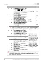
PH1
Photocells connection input with
NC
contact. By default, the input is set to the activation
of photocells during closing (they are not active during opening). The activation of
photocells during closing results in an immediate stop, followed by full opening, or
preventing further closing beginning.
When setting the photocells to operate only during opening (section ‘6.
Adjustment’
P7
–
f1
) the activation of the photocells results in immediate tripping.
Several safety devices are connected consecutively
PH.T
The output for automatic operation test (
PHOTOTEST
) of photocells, connected to
output
PH1
. The operation of the photocells is checked before movement by short-
term disconnection and then reconnection of the power to the photocells transmitter.
Photocells connection diagram—
fig.
26. In settings (section ‘6. Adjustment’
P7
–
f3
) the
activation of the corresponding menu option is performed. After the door closing in
standby mode, the output ‘
PH.T
’ is turned off. The consumption of photocells is less
as the power of the photocell transmitter is turned off. At the beginning of the door
opening the output ‘
PH.T
’ is turned on
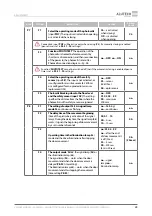
Connection input of the antenna screening conductor
Connection input of the antenna signal conductor
The connector (
fig.
29) used to connect the 24 V DC / 1.2 Ah battery. The battery gives
the opportunity to open the door in the emergency mode (in case of supply voltage
disconnection). The full charge time of the battery is 48 hours
The operation of the devices is shown by LEDs (
fig.
30).
LED
INDICATION DESIGNATION
ILLUMINATES
DOES NOT
ILLUMINATE
A radio control command is received (the LED shines
in red if the console or the remote control button is
not recorded / shines green if the remote control
button is recorded)
is given
not given
PH1
Safety device—photocells (input ‘
PH1
’)
was activated
was
not activated
S
Safety device—
STOP
(input ‘
S
’)
was activated
was
not activated
SBS
command to open, stop, close (input ‘
SBS
’)
is given
not given
Y
ATTENTION!
The state of LEDs, when a command is not given, is shown in bold.
6.
ADjUSTMENT
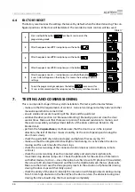
The adjustment of the drive is performed using the board with buttons. A display is used for
indication (
fig.
30).
—
the button to enter the settings menu and to exit the menu.
—
the button to enter the settings and confirm the selected value.
—
the button to move step-by-step to the menu with the zoom; it is also used to
control the opening process when setting the end positions manually.
—
the button to move step-by-step to menu with reduction; it is also used to
control the closing process when setting the end positions manually.
Table 5


