EPC-250 IOI 6-18 All rights reserved © ALTRONIC, LLC 2018
16
(first and seventh). Seven individual control offsets can be programmed. The
desired air pressure is the sum of all offsets.
9.2
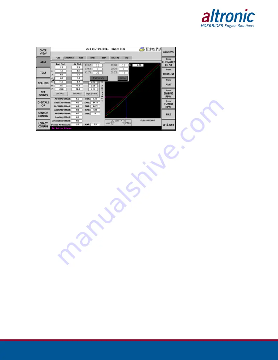
Fuel plot
These values are obtained from the engine manufacturer or from an existing
EPC-200 configuration for the specific engine (air/fuel ratio curve). They must
be entered in ascending order from 1 to 7 (minimum to maximum) to obtain
a positive slope (y=mx+b). The fuel values represent the x coordinates of the
line equation. During operation the program calculates the line segment at
that instant which is indicated by the gray boxed area with an indicating arrow
using the four points of the gray box. This indicator changes as fuel pressure
increases or decreases. This helps the operator know which segment the EPC-
250 is using to calculate the air/fuel ratio in that instant. The calculated value
(desired air manifold pressure) of the 4-point line segment is compared to
the actual air manifold pressure. The difference between the two values is the
input to the PID calculations.
9.3
Air plot
These values are obtained from the engine manufacturer or from the EPC-200 for
the specific engine (air/fuel ratio curve). This value represents the Y value of the
line coordinate. It represents the input value of channel 3 (air manifold pressure).
9.4
Ratio
To enter a specific air/fuel ratio, press the corresponding data box to calculate
the air data point. This value corresponds to the fuel manifold pressure divided
by the air manifold pressure.
9.5
Offset
Each page represents an offset that can be used to manipulate the base air/fuel
offset. The fuel offset is the main parameter for control of the air/fuel ratio. The
desired air pressure is the sum of all offsets.


