


Chapter 2 Installation and Wiring
16
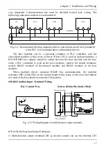
Fig. 2-9 Wiring diagram of analog output terminals
Tips
1) Dialing SW1 to “I” represents current; dialing to “V” represents voltage.
2) Analog input and output signals are easily disturbed by exterior environment, so
shielded cables must be used for wiring and the length of the cables should be as
short as possible.
●
Wiring of Serial Communication Interface
The series of drivers provides users with RS485 serial communication interface, and
can compose master-slave control system. The upper computer (a personal computer or
PLC controller) can be used for real-time monitoring, implementation remote control ,
automatic control and others more complicated operations to drivers in network.
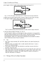
Fig. 2-10 Illustration of wiring between the upper computer and the driver interface:
Fig. 2-10 Wiring diagram between the upper computer and the driver interface
When multiple drivers are connected in one RS485 system, the communication suffers
more interference,
and a maximum of 31 drivers can be connected through RS485 serial bus. Wiring is
0~10V
AO1
GND
PE
Near-end of shield
line is grounded
Driver
Содержание AS600M Series
Страница 96: ...96 ...


