


Appendix 2 Use of MODBUS Communication
87
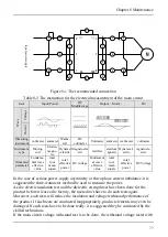
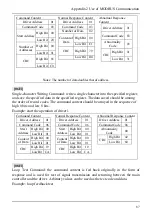
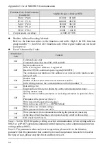
Command Content
Driver Address
01
Command Code
03
Start Address
High Bit 00
Low Bit 20
Number of
Addresses
High Bit 00
Low Bit 01
CRC
High Bit 85
Low Bit C0
Normal Response Content
Driver Address
01
Command Code
03
Number of Data
02
Content of
Data
High Bit 00
Low Bit C1
CRC High
Bit
79
Low
Bit
D4
Abnormal Response
Content
Driver Address
01
Command Code 83
Abnormality
Code
03
CRC
High Bit 01
Low Bit
31
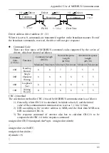
Notes: The number of data doubles that of address.
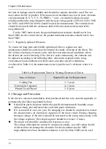
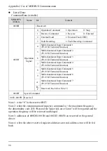
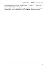
[06H]
Single-character Writing Command: write a single character into the specified register,
and save the specified data in the specified register. The data saved should be among
the order of record codes. The command content should be arrayed in the sequence of
high 8 bits and low 8 bits.
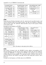
Example: start the operation of driver 1
Command Content
Driver Address
01
Command Code
06
Start
Address
High Bit 00
Low Bit 01
Content
of Data
High Bit 00
Low Bit 01
CRC
High Bit 19
Low Bit CA
Normal Response Content
Driver Address
01
Command Code
06
Start
Address
High Bit
00
Low Bit
01
Content
of Data
High Bit
00
Low Bit
01
CRC
High Bit
19
Low Bit
CA
Abnormal Response Content
Driver Address
01
Command Code
86
Abnormality
Code
00
CRC
High Bit
42
Low Bit
60
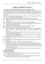
[08H]
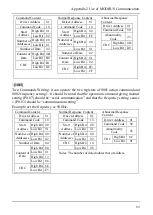
Loop Test Command: the command content is fed back originally in the form of
response and is used for test of signal transmission and returning between the main
controller and the driver. Arbitrary values can be used as the test code and data.
Example: loop feedback test
Содержание AS600M Series
Страница 96: ...96 ...


