background image

0913000-J0    Rev D

40

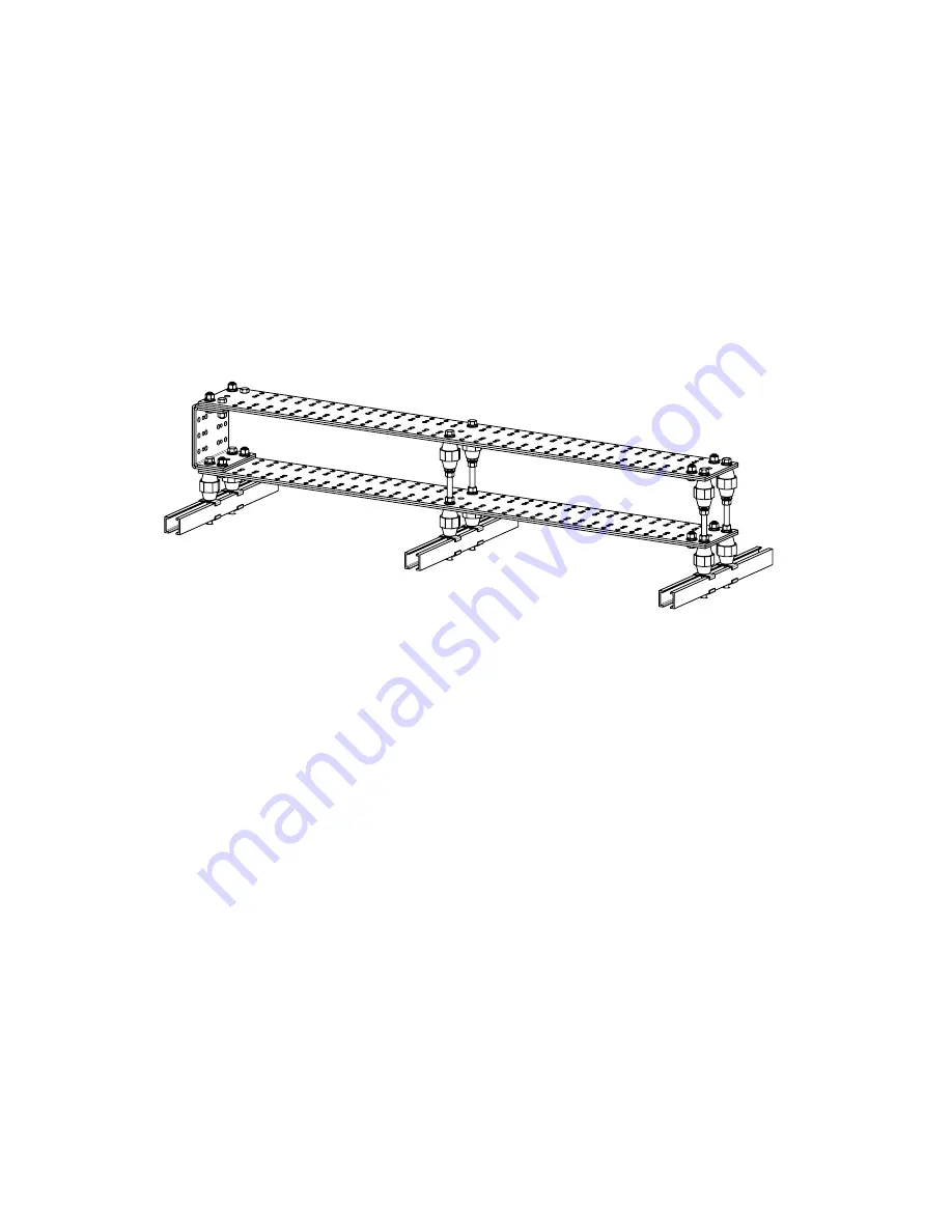
7.5.5  Mounting the External Remote Hot Bar

The external remote hot bar kit option provides a central location to land all the 'hot' cables from the power plant 
and the batteries.
The CXPS-HX Remote Hot Bar Kit, Base (0380213-001) has a capacity of 5000A per kit. An adder kit can be in-
stalled on the existing base kit which increases the total system capacity to 10,000A. The kits can be ordered  with 
or without optional covers.

1.  Before joining bus bar components together, ensure that all contact surfaces on the busbars are clean and 

coated with a thin coat of NO-OX-ID “A” compound (or approved equivalent).

2.  Follow the instructions included with kit# 0380213-F0 to assemble and mount the bus bar on a customer-

supplied auxiliary framing superstructure away from the system.

Note: Requires customer supplied auxiliary frame (2 " x 9/16")

SCALE:

REV

SHEET

SIZE DWG NO.

TITLE:

OF

A

1:8

B

3 6

0380213-F0

REMOTE HOT BAR KIT, 

5000A

THESE DESIGNS AND SPECIFICATIONS ARE
CONFIDENTIAL, REMAIN THE PROPERTY OF

ALPHA TECHNOLOGIES LTD., AND SHALL NOT BE

COPIED OR USED WITHOUT ITS WRITTEN CONSENT

© ALPHA TECHNOLOGIES LTD

CHECKED

DRAWN

DATE

APPROVALS

K. LAM

SEP-10-13
SEP-10-13

S. BIENKO

X.X

X.XX

X.XXX

ANGULAR:

THIRD ANGLE PROJECTION

UNLESS OTHERWISE SPECIFIED

DIM ARE IN INCHES

INTERPRET DIM AND TOL  PER

ASME Y14.5-1994

0.040

1

0.020

0.010

REFER TO BUBBLE

NUMBER IN LEGEND.

ITEM

QTY

  1.75  

  1.06  

  2.0  

  1.75  

  1.06  

   0.56  
   0.44  

  2.0  

  3.0  

CUSTOMER CONNECTIONS SPACINGS

3

2

4

1

5

1

20

2

12

2

12

2

AUXILLARY FRAMING

PROVIDED BY

 CUSTOMER

AUXILLARY FRAMING

PROVIDED BY CUSTOMER

AUXILLARY FRAMING

PROVIDED BY CUSTOMER

15

2

14

2

12

2

19

2

15

2

14

2

5

2

6

2

7

2

14

2

15

2

19

2

15

2

14

2

11

2

14

2

11

2

15

2

19

2

14

2

15

2

13

2

14

4

15

4

19

4

13

2

14

4

15

4

19

4

11

2

12

2

THE NON-EXPLODED ITEMS IN THE ABOVE VIEW ARE

INCLUDED IN 0380213-001 AND SHOULD NOT BE DISASSEMBLED

20

2

NOTES:

1.    REFER TO LEGEND FOR BUBBLE NUMBER DESCRIPTION.

2.    USE THIS DRAWING WHEN INSTALLING TWO ROWS OF REMOTE HOT BARS

3.    SOME DISASSEMBLY OF 0380213-001 AND REUSE OF PARTS IS REQUIRED

       TO ASSEMBLE 0380213-002

4.    LUG SPACING: 130 SETS OF 1/2-13 HOLES ON 1-3/4" CENTERS OR

                                  130 SETS OF 3/8-16 HOLES ON 1" CENTERS

5.    TIGHTEN 5/8-11 BOLTS THAT ATTACH TO 5/8-11 NUTS TO 150-154 FT-LBS

       TIGHTEN 5/8-11 BOLTS THAT ATTACH TO GLASTIC STANDOFFS TO 35 FT-LBS

REMOTE HOT BUSKIT, NO COVER,

5000A, ADDER ASSEMBLY, VERTICAL

REVISIONS

LTR

DESCRIPTION

BP

DWN

DATE

CHK

LEGEND

BUBBLE

P/N

DESCRIPTION

1

5610302-001 PLASTIC COVER, MAIN

2

5610313-001 PLASTIC COVER, SIDE

3

5900660-001

BUSBAR, MAIN

4

5900661-001 BUSBAR, INNER BEND

5

5900662-001 BUSBAR, OUTER BEND

6

5900681

CLIP, AUX FRAMING

7

5902040-001

BUSBAR, JOINER

8

6300022

SCREW, 1/4-20x0.75"

9

6300113

SCREW, 5/8-11x3.0"

10

6300174

SCREW, 5/8-11x1.0"

11

6300175

SCREW, 5/8-11x1.5"

12

6300176

SCREW, 5/8-11x2"

13

6300177

THREADED ROD, 6.5"

14

6330069

WASHER, LOCK, 5/8"

15

6330086

WASHER, FLAT, 5/8"

16

633-011-12

WASHER, FLAT, 1/4"

17

633-035-19

WASHER, LOCK, 1/4"

18

6340028

NUT, 1/4-20

19

6340033

NUT, 5/8-11

20

6400030

3.5" GLASTIC STANDOFF

21

6400068

3" GLASTIC STANDOFF

A

B

C

D

E

1

2

3

4

5

D

A

C

E

B

1

3

5

4

2

DO NOT SCALE DRAWING

Figure 28  —  External hot bar (2 kits shown)

Содержание CXPS-HX 48-2500

Страница 1: ...Your Power Solutions Partner CXPS HX 48 2500 Distributed Power System Installation Operation Manual Part 0913000 J0 Effective 03 2016 member of The Group...

Страница 2: ......

Страница 3: ...ormation only and is subject to change without notice While reasonable efforts have been made in the preparation of this document to assure its accuracy Alpha Technologies assumes no liability resulti...

Страница 4: ...3 4 3 Cordex System Controller 15 4 4 Cordex HP Controller CXC HP 17 4 5 External Peripherals 18 4 6 Redundant Input Power Module 20 4 7 Shelf Bay ID 20 5 Pre Installation Preparation 21 5 1 Site Sele...

Страница 5: ...tery Polarity and Connect 42 8 4 Final Configuration and Test 42 8 5 Shelf ID Connection 43 9 Test and Commissioning Overview 44 9 1 System 44 9 2 Battery 44 9 3 Documentation 44 10 Maintenance 45 10...

Страница 6: ...ring power system bay to concrete floor 25 Figure 15 Battery disconnect purchased separately connections 26 Figure 16 Tandem system busbar installation bay shown with panels removed 27 Figure 17 Batte...

Страница 7: ...NG WARNING presents safety information to PREVENT INJURY OR DEATH to personnel Warnings are indicated by a shock hazard icon the word WARNING and a rule beneath which the information appears CAUTION C...

Страница 8: ...turer s safety recommendations when working around battery systems Do not smoke or introduce an open flame when batteries especially vented batteries are charging When charging batteries vent hydrogen...

Страница 9: ...bus work is required An optional external return bus is available Cable access is from the top and load connections are terminated from the side or rear of the bay Hot swappable Cordex power modules p...

Страница 10: ...N A 277 480 30 3W N PE 8 N A 30 1 208 277 30 60Hz 1 8 N A CXPS HX 48 2000 12kW 480 4 rectifier shelves with AC distribution panel 4 480 50 3W N PE 6 1 5 1 25 KO 8 480 30 3W N PE 8 1 5 1 25 KO CXPS HX...

Страница 11: ...ormation Cordex HP 12kW 480 3P rectifier See the 12kW datasheet on the Alpha website for more detailed information System level alarms controls Alarms control parameters are user programmable through...

Страница 12: ...supplied Termination With 4 kits 266 sets of 1 2 13 holes on 1 3 4 centers OR 266 sets of 3 8 16 holes on 1 centers Unit capacity per base kit 2500A per kit Ultimate capacity 4 kit limit 10 000A Agenc...

Страница 13: ...ired input voltage depends on the rectifier options chosen at the time of ordering Refer to the specifications in Section 3 on page 8 An optional AC distribution assembly at the top of each power bay...

Страница 14: ...ifier manual included with the system docu mentation package The controller provides central control of the rectifiers output level load sharing temperature compensation and alarm reports A CAN bus ca...

Страница 15: ...ls per bay Plug in bullet breakers 18 breaker poles per panel Up to a maximum of 6 fuse panels per bay Up to a maximum of 2 panels per bay with the AC distribution option Up to a maximum of 4 panels p...

Страница 16: ...e primary bay Figure 5 Distribution shunts 4 2 3 Low Voltage Load Disconnect LVLD Option The LVLD feature provides automatic disconnect of the system loads after a prolonged power failure when the bat...

Страница 17: ...provides details of all major and minor alarms Illuminated LED Alarm Green OK no alarms Yellow Minor alarm no Major alarms Red Major alarm Progress and status indication The LED lights are also used...

Страница 18: ...with a remote screen display that is an enhanced version of the CXC front panel display Ethernet port An Ethernet port is located inside the front panel This port is designed to connect the controlle...

Страница 19: ...nerate electrical signals through relays The most commonly used ADIO peripheral is the L ADIO for low voltage systems which includes 8 digital inputs 4 voltage sensors 4 temperature sensors 4 current...

Страница 20: ...er Figure 9 L ADIO I O Peripheral Power Input LVD Override 3 LED Status Indicators Reset CAN Ports Analog Inputs Four voltage inputs V1 V4 are provided for a variety of voltage monitoring requirements...

Страница 21: ...utton A reset button is located on the front panel It takes approximately 15 seconds before the unit is reacquired after pressing the reset button During a reset condition the L ADIO will keep relays...

Страница 22: ...D peripheral enables users to identify individual 12kW 480 3 phase rectifier modules by their specific bay and shelf location within the system This peripheral is an independent module which broad cas...

Страница 23: ...space must be provided at the front and rear of the power system to meet the cooling requirements of the rectifiers in the power system and to allow easy access to the power system components Conside...

Страница 24: ...que wrench 3 8 drive 0 100 ft lb for system connections Insulating canvases as required 2 x 2 1 x 1 3 x 3 etc Cutters and wire strippers 14 to 22 AWG 2 5 34 mm2 Insulated hand tools listed below Combi...

Страница 25: ...nal damage In the unlikely event of internal damage inform the carrier and contact Alpha Technologies for advice on the impact of any damage 5 6 General Receipt of Shipment The inventory included with...

Страница 26: ...me is earthquake qualified when properly anchored to a 3000 psi 2 11 kg per sq mm concrete floor The anchoring kit and procedures in this section are for a seismic installation but apply equally well...

Страница 27: ...1 Securing the Bay to the Floor NOTE It is extremely important that the bay be properly shimmed in order to prevent any frame distortion If the floor is not level shims may be required 1 Place the ba...

Страница 28: ...ct purchased separately connections 6 2 2 LVBDs purchased separately If battery disconnect contactors are used 1 Connect a secondary power source to the CXC 2 Connect battery disconnect panels to the...

Страница 29: ...ULAR THIRD ANGLE PROJECTION UNLESS OTHERWISE SPECIFIED DIM ARE IN INCHES INTERPRET DIM AND TOL PER ASME Y14 5 1994 0 040 1 0 020 0 010 REFER TO BUBBLE NUMBER IN LEGEND ITEM QTY 1 1 2 1 4 1 5 4 6 4 4 1...

Страница 30: ...tery breakers DC circuit breakers and fuses on the distribution panels are either in the OFF position or removed Use a corrosion inhibiting agent such as NO OX or NCP 2 on all battery terminal connect...

Страница 31: ...s coiled up in the power section of the bay 2 Connect CXC temperature probes from CXC to battery termination post negative 3 Pick a location at mid height on one or more battery strings which will pro...

Страница 32: ..._______________________ Battery location and or number _______________________________________________________________ No of cells _______________ Type __________________________ Date new ____________...

Страница 33: ...aling wires for example alarms from the CXC Controller interfacing with the outside world exit the frame through the top or bottom 7 1 2 Calculating Output Wire Size Requirements Although DC power wir...

Страница 34: ...WG or 4 0 211600 107 2 120 313 MCM or kcmil 313600 159 150 or 185 350 MCM or kcmil 350000 177 36 185 373 MCM or kcmil 373700 189 185 or 240 500 MCM or kcmil 500000 253 36 300 535 MCM or kcmil 535300 2...

Страница 35: ...protection fuse or circuit breaker 750 MCM is recommended This is the minimum require ment Other factors including length of cable and special grounding requirements of the load must be factored in U...

Страница 36: ...es or directly to each rectifier shelf For both options refer to the AC Input specification in Section 3 on page 8 NOTE The recommendations for input breakers and wire sizes in Table A are for referen...

Страница 37: ...are off and locked out at the AC Input Panel Wire one side at a time with only one door open 1 Bring AC wires through the knockouts in the top of the assembly 2 Connect to the terminal blocks as shown...

Страница 38: ...n cables to the common return bus or see drawings 0250014 771 04 0250014 701 04 and 0250014 741 04 or to the external battery return bus bar if that option is in place drawing 0380214 F0 Both bus bars...

Страница 39: ...ards the back as shown in Figure 23 There are a total of 4 positions 8 cables back to back to land the DC return cables The dimensions for holes are 1 2 on 1 75 centers and 3 8 on 1 centers Figure 24...

Страница 40: ...d 3 8 on 1 centers There are a total of 4 positions 8 cables back to back to land the DC return cables The dimensions for holes are 1 2 on 1 75 centers and 3 8 on 1 centers Figure 25 DC connection wit...

Страница 41: ...O COVER 2500A 3 VERTICAL ROWS REVISIONS LTR DESCRIPTION BP DWN DATE CHK B C D E D C E B 1 3 5 4 2 DO NOT SCALE DRAWING Note Requires customer supplied auxiliary frame 2 x 9 16 Figure 27 Internal retur...

Страница 42: ...luded with kit 0380213 F0 to assemble and mount the bus bar on a customer supplied auxiliary framing superstructure away from the system Note Requires customer supplied auxiliary frame 2 x 9 16 X X X...

Страница 43: ...198 SETS OF 3 8 16 HOLES ON 1 CENTERS 5 TIGHTEN 5 8 11 BOLTS THAT ATTACH TO 5 8 11 NUTS TO 150 154 FT LBS TIGHTEN 5 8 11 BOLTS THAT ATTACH TO GLASTIC STANDOFFS TO 35 FT LBS REMOTE RETURN BUSKIT NO COV...

Страница 44: ...et the battery parameters float and equalize voltages to the capacity Peukert exponent open circuit voltage levels specified by the battery manufacturer 8 4 Final Configuration and Test 1 Configure ot...

Страница 45: ...and rectifier slot IDs to CXC HP Rack mounted Shelf ID PCB Bay ID 1 manually set 8 5 Shelf ID Connection The shelf bay ID comes factory installed If shelves are installed in more than one bay then set...

Страница 46: ...ity cell voltage charge current and temperature Battery warranty may be void if batteries are not initially charged following the manufacture s guidelines with proper records maintained Some VRLA batt...

Страница 47: ...ance information 10 2 Batteries It is recommended that checks are made every six months for battery voltage conductance temperature imped ance connections etc See battery manufacturer s manual for gen...

Страница 48: ...Federal Communications Commission for the USA GSM Group Speciale Mobile global system for mobile communications HVSD High voltage shutdown IEC International Electrotechnical Commission IEEE Institute...

Страница 49: ...mages or consequential damages based upon equipment failure during or after the warranty period No other obligations are expressed or implied Warranty also does not cover damage or equipment failure d...

Страница 50: ...s are certified to CSA C22 2 No 107 3 and UL 1778 As part of the reciprocal US Canada agreement regarding testing laboratories the Standards Council of Canada Canada s national accreditation body gran...

Страница 51: ...ES INTERPRET DIM AND TOL PER ASME Y14 5 1994 0 040 1 0 020 0 010 PRODUCT TO BE FABRICATED ACCORDING TO ATL PRODUCTION STANDARD 0700001 1 NOTES UNLESS OTHERWISE SPECIFIED 28 0 TYP 23 5 FRONT VIEW CXPS...

Страница 52: ...HNOLOGIES LTD CHECKED DRAWN DATE APPROVALS K LAM NOV 21 13 NOV 21 13 S BIENKO X X X XX X XXX ANGULAR THIRD ANGLE PROJECTION UNLESS OTHERWISE SPECIFIED DIM ARE IN INCHES INTERPRET DIM AND TOL PER ASME...

Страница 53: ...USED WITHOUT ITS WRITTEN CONSENT ALPHA TECHNOLOGIES LTD CHECKED DRAWN DATE APPROVALS FV 2 18 2014 2 18 2014 DX THIRD ANGLE PROJECTION UNLESS OTHERWISE SPECIFIED DIM ARE IN MM INTERPRET DIM AND TOL PER...

Страница 54: ......

Страница 55: ......

Страница 56: ...s Tel 357 25 375 675 Fax 357 25 359 595 www alpha com Alpha Technologies Pty Ltd Suite 2 32 34 Peter Brock Drive Eastern Creek NSW 2766 Australia Tel 61 2 8599 6960 www alpha com Alpha Innovations Bra...

Отзывы: