


11
2. FEATURES
2.5
Communication / Interface Options
,
continued
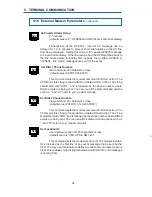
Pin 1
Pin 1
RJ-45
(External Alarms)
MMJ
(External IID)
Fig. 5
CFR-UPS Connector Identification and Pin-out
Rear Panel Connectors:
Below are the various communication connectors as they appear on the
back of the CFR-UPS. The photographs show the pin numbering for the different
connector types.
NOTE: Use only fully shielded cables to make connections to any of the
DE-9 connectors (RS-232 port or LAN interface).
Pin 1
Pin 5
Pin 6
Pin 9
DE-9 Connector (RS-232 and LAN)
RS–232 Serial Connector
LAN Interface Connector
External IID Connector
External Alarms Connector
62
5. RS-232 TERMINAL COMMUNICATION
5.13 Event Descriptions (Alarms),
continued
Input Line Fail - Indicates that the UPS switched to backup power to protect
the equipment for one (or more) of the above conditions. * *
Normal Line Mode - Indicates that the UPS is drawing power from the AC line
and charging the batteries.
Test Mode - Indicates the UPS was put into a test mode condition either by
the TEST SCHEDULE routine or by pressing the TEST button on the Intelligent Interface
Device's panel. The unit will switch to backup power while in the test mode. * *
Float Charge Mode - This is the normal operating mode of the battery charger.
During LINE PRESENT operation, the batteries constantly receive a "Float" charge
voltage to ensure that backup power is available when required.
Service Codes (1-6) - These codes indicate a potential fault within the UPS.
Call Alpha Customer Support and report any displayed Service Codes. Also refer to
the Troubleshooting section (6.7) of the manual.
Serv Code 1 - Phase Lock Loop Failure. The phase lock loop circuitry has
failed to lock onto the AC input LINE due to instability of the frequency. If the UPS is
operating from a generator, check the frequency and adjust it if necessary.
Serv Code 2 - Micro software reset. The internal “watch dog” circuit has
detected a fault and reset the software. Contact Alpha to help determine the cause of
the fault.
Serv Code 3 - Micro hardware reset. A micro hardware reset is activated as
part of the power on condition. If this alarm occurs during normal operation, it may
indicate a malfunction in the hardware circuitry. Contact Alpha to help determine the
cause of the fault.
Serv Code 4 - Power board EEPROM fault. The EEPROM on the power board
contains the unit configuration information. If this fault occurs, it signifies either the
configuration information has been corrupted, the EEPROM has malfunctioned, or
there is a loose connection inside the UPS.
Serv Code 5 - Power board hardware fault. The control circuitry on the power
board has detected a hardware fault condition which impedes correct operation of the
UPS.
Serv Code 6 - Neg DC supply rail fail. The negative voltage power supply to
the microcontroller has malfunctioned.
EMGNCY POFF - Emergency power shutdown.
OUTV SHTDWN - See menu 505 & 506 (see section 5.9).
* * Indicates events that cause the UPS to operate in “LINE FAILURE” mode.


